


Service
22 Operator’s Manual
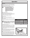
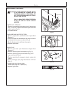
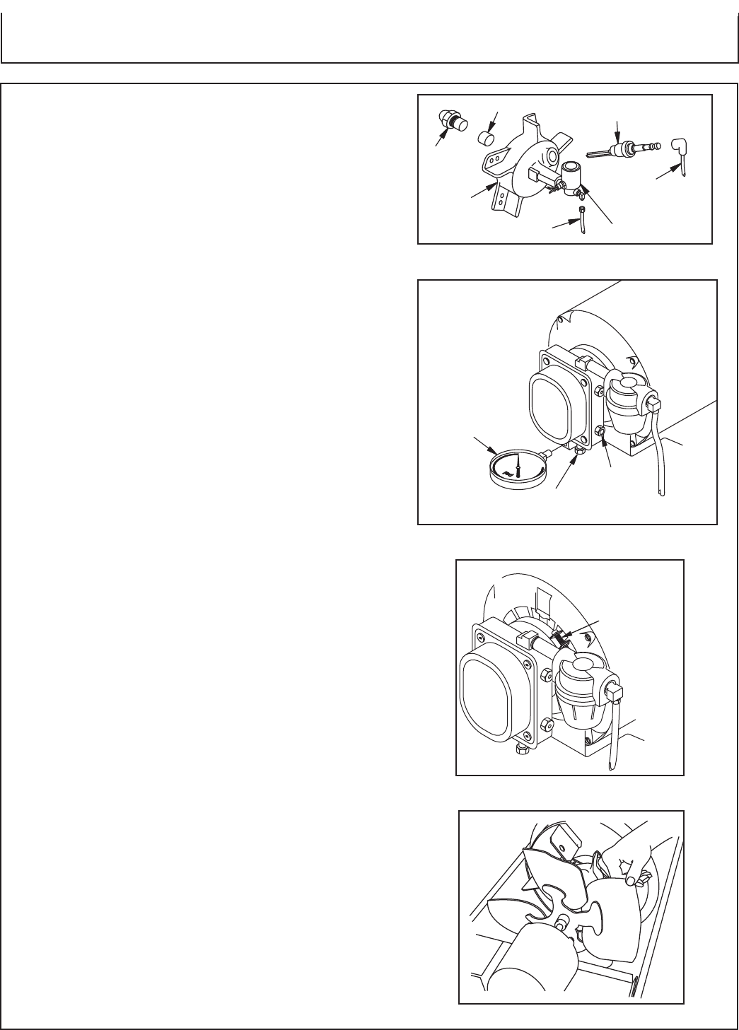
NOZZLE:
1. Remove upper shell. (see Mantenance: Upper Shell
Removal).
2. Remove fuel line from solenoid valve using 7/16"
wrench.
3. Remove spark plug wire from spark plug.
4. Remove spark plug from burner head using 13/16" open-
end wrench.
5. Remove five screws using 5/16" nut-driver and remove
burner head from combustion chamber.
6. Place burner head into vise and lightly tighten.
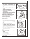
7. Carefully remove nozzle from burner head using 5/8"
socket wrench (Fig. 7).
8. Inspect nozzle for damage. If damaged or clogged, replace
nozzle.
9. Make sure plug is in place on burner head.
10. Replace nozzle into burner head and tighten firmly
(175-200 inch-pounds).
11. Attach burner head to combustion chamber.
12. Install spark plug in burner head.
13. Attach spark plug wire to spark plug.
14. Attach fuel line to solenoid valve. Tighten firmly.
15. Replace upper shell.
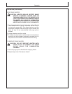
PUMP PRESSURE ADJUSTMENT:
1. Remove pressure gauge plug from fuel pump port marked
“GAUGE.”
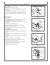
2. Install pressure gauge to fuel pump port marked “GAUGE
”
(Fig. 8).
3. Start heater. Allow motor to reach full speed.
4. Adjust pressure. Use small flat blade screwdriver to
turn slotted screw at fuel pump pressure adjusting port.
Turn screw clockwise to increase pressure. Turn screw
counterclockwise to decrease pressure. See specifications
in Figure 8 for correct pressure for each model.
5. Stop heater.
6. Remove pressure gauge. Replace pressure gauge plug
in fuel pump port marked “GAUGE.”
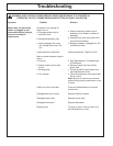
PUMP:
(Procedure if Pump is Binding)
1. Remove upper shell (Maintenance: Upper Shell
Removal).
2. Loosen hex screw on flange clamp at rear of motor with
5/16" nut-driver (Fig. 9).
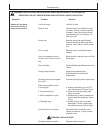
3. Turn fan with hand (Fig. 10).
4. If fan turns freely, tighten screw on flange clamp.
5. If fan does not turn freely, replace pump.
6. Replace upper shell.
(Fig. 7)
Spark Plug
Burner
Head
Fuel Line
Solenoid Valve
Plug
Nozzle
Spark Plug
Wire
(Fig. 8)
Pump Pressure
100 PSI
Pressure
Gauge
Fuel Pump Port
Marked "GAUGE"
Fuel Pump
Port Marked
"PRESS ADJ"
(Fig. 9)
(Fig. 10)
Hex Screw
On Flange
Clamp