


6
• To remove the shaft sleeve (126) it is necessary to evenly
heat the outside of the sleeve, with a hand propane torch,
while prying between the shaft shoulder and the sleeve.
NOTICE: EXERCISE CARE HANDLING THE HOT
SHAFT SLEEVE.
• Removal of the 4 motor adapter screws (371) and motor
adapter (108) from the motor completes the close coupled
unit disassembly.
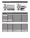
• Disassembly of the bearing frame assembly is accomplished
by removing the 4 frame adapter screws (371) and remov-
ing the frame adapter (108) from the bearing frame (228).
• Remove the 4 bearing cover (370C) screws, being careful
not to damage the lip seal (139). Inspect lip seal for damage
and replace as required.
• Remove the shaft assembly from the bearing frame, by pull-
ing the motor end of shaft out of the housing.
• Being careful not to damage the shaft, remove the snap ring
(361) and outer bearings (112) from the shaft. If required
remove the inner bearing (168). Inspect the bearings for
wear or damage and replace as necessary.
• Inspect the inner lip seal (138) and replace as required.
• Disassembly is complete.
Reassembly
• Reassemble the bearing frame assembly in reverse order
of disassembly. Use appropriate tools for bearing installa-
tion and press ONLY on inner bearing race. Press bearings
squarely and completely onto the shaft.
• If the shaft sleeve was replaced, it is required that the new
sleeve be bonded to the shaft using Loctite
TM
#243 or
equivalent. Following the manufacturer’s instructions in the
preparation of the sleeve and shaft, apply bonding agent to
the surfaces then slide the sleeve over the shaft. Remove all
excess bonding agent.
• Install the shaft assembly into bearing frame. DO NOT
damage the inner lip seal.
• Insert and tighten the 4 bearing cover screws.
• Install the bearing adapter, nameplate towards the TOP,
using the 4 screws.
• Inspect and remove any debris from the seal housing sta-
tionary seat bore. Lubricate the outside diameter of the new
stationary seat with a good quality O-ring lubricant and
press seat squarely and completely into the seal housing.
With a clean, lint free cloth remove any debris or lubricant
from the seat face. DO NOT scratch the face.
• Install a new seal housing O-ring on housing, then care-
fully slide seal housing over shaft and attach housing to the
motor adapter with the 4 screws. DO NOT damage the
mechanical seal stationary seat.
• Install the new shaft sleeve O-ring.
• Slide the new mechanical seal rotary assembly over shaft
sleeve. Apply Loctite™ 7649 and allow to dry. Apply
Loctite™ #243 to the motor shaft thread and then screw
on the impeller by turning impeller CLOCKWISE. Torque
the impeller to 12 ft lbs (1.7 kg/m).
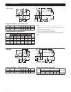
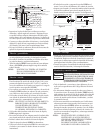
• Shim pack (330) permits renewal of impeller clearance to
compensate for impeller or casing wear. The shim thick-
nesses, in the shim pack, range from 0.003" to 0.025"
(0.08 mm to 0.64 mm). The factory shim pack thickness
is approximately 0.060" (1.52 mm). To set the suggested
nominal impeller clearance of 0.020" (0.51 mm) proceed as
follows:
• Establish a shim pack thickness that allows for the impel-
ler to just touch the inside of the casing surface, when
pump is assembled.
• Add an additional 0.020" (0.51 mm) thickness of shims.
• When the proper impeller clearance has been achieved,
install and tighten the 4 casing screws.
• Install the 4 bearing frame holddown bolts for the frame
mounted units or the 4 motor holddown bolts for the close
coupled units.
• On frame mounted units, check the coupling alignment as
specifi ed in the “MOTOR TO PUMP – SHAFT
ALIGNMENT” section of this manual.
• Inspect unit rotation for binding and correct as required.
• Reinstall the safety guard.
• Reassembly is complete.
Troubleshooting Guide
DISCONNECT AND LOCKOUT
ELECTRICAL POWER BEFORE
ATTEMPTING ANY MAINTENANCE.
FAILURE TO DO SO CAN CAUSE A
SHOCK, BURN OR DEATH.
SYMPTOM
MOTOR NOT RUNNING
See Probable Cause – 1 through 5
LITTLE OR NO LIQUID DELIVERED BY PUMP
See Probable Cause – 6 through 13
POWER CONSUMPTION TOO HIGH
See Probable Cause – 3, 13, 14, 15, 18
EXCESSIVE NOISE and VIBRATION
See Probable Cause – 3, 6, 7, 8, 10, 12, 14, 16, 17, 18
PROBABLE CAUSE
1. Motor thermal protector tripped
2. Open circuit breaker or blown fuse
3. Impeller binding
4. Motor improperly wired
5. Defective motor
6. Pump is not primed, air or gases in pumpage
7. Discharge, suction plugged or valve closed
8. Incorrect rotation (3 phase only)
9. Low voltage or phase loss
10. Impeller worn or plugged
11. System head too high
12. NPSH
A
too low – Suction lift or suction losses excessive
13. Incorrect impeller diameter
14. Discharge head too low – excessive fl ow rate
15. Fluid viscosity, specifi c gravity too high
16. Worn bearing
17. Pump, motor or piping loose
18. Pump and motor shafts misaligned
WARNING
Hazardous
voltage