


5
WARNING
Hazardous
machinery
NOTICE: UNIT ROTATION IS CLOCKWISE WHEN
VIEWED FROM MOTOR END. INCORRECT
ROTATION MAY CAUSE DAMAGE TO THE
PUMP AND VOIDS WARRANTY.
• Three Phase Motors ONLY:
To check the pump rotation, observe pump while switch-
ing the electrical power ON then OFF quickly. If incorrect,
have a qualifi ed electrician interchange two of the three
motor power wires.
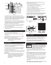
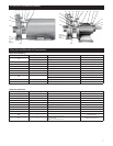
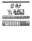
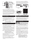
Motor to Pump – Shaft Alignment
• After completion of the frame mounted unit baseplate
installation, the motor and pump shaft alignment MUST
be checked, see Figure 6, and the coupling spacer must
be reinstalled.
• Before checking shaft alignment, insure that the foun-
dation, pump and motor holddown bolts are properly
tightened.
• If realignment is required, ALWAYS make the required
adjustments to the motor, shimming as necessary.
Figure 6
• To check for PARALLEL misalignment, place a dial
indicator on one coupling hub, rotate the hub 360° while
observing the indicator readings from the outside diameter
of the other hub. Parallel alignment requires a Total
Indicator Reading (TIR) of 0.005" (0.13 mm), or less.
• To check for ANGULAR misalignment, place a dial indica-
tor on one coupling hub, rotate the hub 360° while observ-
ing the indicator readings from the face of the other hub.
Angular alignment requires 0.005" (0.13 mm) TIR, or less.
• Correct alignment is achieved when parallel and angular
TIR requirements are satisfi ed and motor holddown bolts
are tight.
NOTICE: RECHECK SHAFT ALIGNMENT AFTER
MAKING ANY ADJUSTMENTS.
Operation
DO NOT OPERATE UNIT WITHOUT
SAFETY GUARD IN PLACE. TO DO
SO CAN CAUSE SEVERE PERSONAL
INJURY OR DEATH.
NOTICE: PUMP MUST BE COMPLETELY PRIMED
BEFORE OPERATION.
DO NOT OPERATE PUMP AT OR
NEAR ZERO FLOW. TO DO SO CAN
CAUSE EXTREME HEAT, DAMAGE TO
THE PUMP, PERSONAL INJURY OR
PROPERTY DAMAGE.
• After stabilizing the system at normal operating conditions,
check the piping and coupling for correct alignments. If
necessary, adjust pipe supports and realign the shafts
following the procedures provided.
Maintenance
• Close coupled pump motors and frame mounted pump
frames have permanently lubricated bearings. Additional
lubrication is not necessary or possible.
• Follow the coupling and motor manufacturer’s
recommendations regarding maintenance.
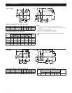
Disassembly
DISCONNECT AND LOCKOUT
ELECTRICAL POWER BEFORE
ATTEMPTING ANY MAINTENANCE.
FAILURE TO DO SO CAN CAUSE A
SHOCK, BURN OR DEATH.
CASING MAY CONTAIN HAZARDOUS
FLUIDS THAT CAN CAUSE SERIOUS
PERSONAL INJURY OR PROPERTY
DAMAGE.
• Drain and fl ush system, as required.
• For close coupled or frame mounted units:
• Remove the motor or bearing frame holddown bolts
• Remove the coupling guard and coupling spacer
• Remove the 4 casing screws (370), then utilizing the slots
provided about the casing (100), pry the back pull-out as-
sembly from casing. Carefully remove the casing shims.
NOTICE: IMPELLER COMPRESSES THE MECHANICAL
SEAL SPRING – BE PREPARED FOR THE
IMPELLER TO SPRING FROM THE SHAFT
WHEN UNSCREWED.
• To remove the impeller it is necessary to heat the center
hub area with a hand propane torch for approximately 30
seconds. Unscrew the impeller (101) from the shaft, turn the
impeller COUNTERCLOCKWISE while holding the shaft.
Motors have a screwdriver slot or hex provided under the
motor end cap. Examine the impeller for wear or damage and
replace as necessary. Discard the shaft sleeve O-ring (412A).
NOTICE: EXERCISE CARE HANDLING HOT
IMPELLER.
• To remove the mechanical seal, remove the 4 seal housing
screws (370H) and slide the seal housing assembly off the
shaft. Discard the rotary half of the seal and the seal hous-
ing O-ring (513). With an appropriately sized screwdriver
handle, push the stationary half of the seal from the seal
housing and discard it.
Parallel
Angular
Hazardous machinery
can cause personal
injury or death.
WARNING
Extreme heat can
cause personal injury
or property damage.
WARNING
Hazardous fluids can
cause personal injury
or property damage.
WARNING