


3
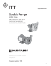
DESCRIPTION and SPECIFICATIONS
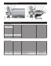
The Models ICS, close coupled, and ICS-F, frame mounted,
are single stage, end suction pumps designed for ultra pure
water systems, beverage processing, chemical service and
selected OEM applications.
The pumps are of back pullout confi guration, with NPT
suction and discharge connections and have investment cast
AISI Type 316 stainless steel casings, open impellers and
seal housing. All pumps are equipped with O-ring shaft
sleeve protection and are available with a variety of optional
mechanical seals.
Close coupled units are equipped with C-face NEMA motors
with threaded shaft extensions. Frame mounted units can be
baseplate mounted and are available with spacer couplings or
may be belt driven.
Close coupled units are available with single and three phase
ODP, TEFC and explosion proof motors. Consult with your
distributor/dealer for additional information.
NOTICE: INSPECT UNIT FOR DAMAGE AND
REPORT ALL DAMAGE TO CARRIER
IMMEDIATELY.
MAXIMUM OPERATING LIMITS
Liquid Temperature:
212° F (100° C) – standard mechanical seal
250° F (120° C) – OPTIONAL mechanical seal
Operating Pressure: 175 PSI (1203 kPa)
Starts per Hour: 20, evenly distributed
Installation – General
• Locate the pump as near to the liquid source as possible.
• If pump repriming capability is required, the pump suction
MUST be below the source of the liquid level.
• Protect the pump and piping from freezing temperatures.
• Allow adequate space around the unit for service and
ventilation.
Close Coupled Units
• Units may be installed horizontally, inclined or vertically.
DO NOT MOUNT MOTOR BELOW
PUMP. FLUID LEAKAGE ONTO
MOTOR CAN CAUSE A SHOCK,
BURN OR DEATH.
• Unit foundation must be fl at and substantial to avoid pipe
strains when bolts are tightened. Use rubber mounts under
motor to minimize noise and vibration.
• Tighten motor holddown bolts BEFORE connecting the
suction and discharge piping.
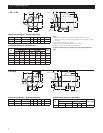
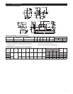
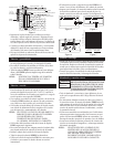
Frame Mounted Units
• Place the baseplate upon the foundation and disconnect the
coupling halves. DO NOT reconnect the coupling until the
alignment procedures have been completed.
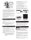
• It is recommended that the baseplate be grouted to a
foundation with a solid footing, per Figure 1.
SAFETY INSTRUCTIONS
TO AVOID SERIOUS OR FATAL PERSONAL INJURY OR
MAJOR PROPERTY DAMAGE, READ AND FOLLOW
ALL SAFETY INSTRUCTIONS IN THE MANUAL AND ON
THE PUMP.
This is a SAFETY ALERT SYMBOL. When
you see this symbol on the pump or in the
manual, look for one of the following signal
words and be alert to the potential for
personal injury or property damage.
Warns of hazards that WILL cause serious
personal injury, death or major property
damage.
Warns of hazards that CAN cause serious
personal injury, death or major property
damage.
Warns of hazards that CAN cause personal
injury or property damage.
NOTICE: INDICATES SPECIAL INSTRUCTIONS
WHICH ARE VERY IMPORTANT AND
MUST BE FOLLOWED.
THIS MANUAL IS INTENDED TO ASSIST IN THE
INSTALLATION AND OPERATION OF THIS UNIT.
THOROUGHLY REVIEW ALL INSTRUCTIONS AND
WARNINGS PRIOR TO PERFORMING ANY WORK
ON THIS PUMP.
MAINTAIN ALL SAFETY DECALS.
Install, ground and wire accord-
ing to local and National Electrical
Code Requirements.
Install an all leg disconnect switch
near the pump.
Disconnect and lockout electrical
power before installing or servicing
the pump.
Electrical supply must match motor’s
nameplate specifi cations. Incorrect
voltage can cause fi re, damage motor
and void the warranty.
Single phase pump motors are equipped with an
automatic thermal protector, which opens the motor’s
electrical circuit when an overload condition exists.
This can cause the pump to start unexpectedly.
DANGER
WARNING
CAUTION
WARNING
Hazardous voltage
can shock, burn or
cause death.
WARNING
Hazardous
voltage