


4
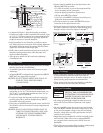
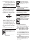
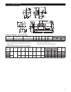
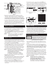
Figure 1
• As depicted in Figure 1, place the baseplate on wedges,
locating two wedges at each foundation bolt location. A gap
of ¾" to 1½" (19 mm to 64 mm) is recommended between
the baseplate and the foundation for grouting. Adjust the
wedges as necessary to level the baseplate.
• Inspect baseplate for any distortion, and adjust as neces-
sary. Make sure that any necessary fi nal coupling alignments
are possible within the motor movements and shim limits.
Tighten the 4 foundation bolts fi nger tight.
• Build a dam around foundation and pour grout under the
baseplate, insuring that the areas under the pump and
motor are fi lled completely.
• Allow grout to harden for 48 hours before tightening
4 foundation bolts.
Piping – General
• For maximum pump capacity, piping should not be smaller
than the pump suction and discharge.
• To minimize pipe friction losses, avoid unnecessary pipe
and fi ttings.
• All piping MUST be independently supported and MUST
NOT place any piping loads on pump.
NOTICE: DO NOT FORCE PIPING INTO PLACE AT
PUMP SUCTION AND DISCHARGE
CONNECTIONS.
Piping – Suction
• Short and direct suction piping is recommended. For
suction lifts of over 10' (3 m) and liquid temperatures over
120° F (49° C), consult pump performance curve for net
positive head required (NPSH
R
).
• If a pipe size larger than the pump suction is required, an
eccentric pipe reducer, with the straight side up, MUST
be installed at the pump suction.
• If the pump is installed below the liquid source, install a full
fl ow isolation valve in the suction for pump inspection and
maintenance.
NOTICE: DO NOT USE THE ISOLATION VALVE TO
THROTTLE PUMP. THIS MAY CAUSE LOSS
OF PRIME, EXCESSIVE TEMPERATURES
AND DAMAGE TO PUMP, VOIDING
WARRANTY.
• If pump must be installed above the liquid source, the
following MUST be provided:
• To avoid air pockets, no part of the piping should be
above the pump suction connection.
• Slope the piping upward from liquid source.
• All pipe joints MUST be airtight.
• Use a foot valve ONLY if necessary for priming or to
hold prime during intermittent duty.
• The suction strainer or suction bell MUST be at least
3 times the suction pipe diameter area.
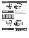
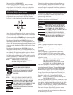
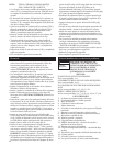
• Insure that the size and minimum submergence over suc-
tion inlet is suffi cient to prevent air from entering pump
through a suction vortex. See Figures 2 through 5.
Piping – Discharge
• Install a check valve, suitable to handle the fl ow and liquids,
to prevent backfl ow. After the check valve install an
appropriately sized gate valve to be used to regulate the
pump capacity, pump inspection and maintenance.
• When required, the pipe increaser should be installed be-
tween the check valve and the pump discharge.
Wiring and Grounding
DISCONNECT AND LOCKOUT
THE ELECTRICAL POWER BEFORE
ATTEMPTING ANY MAINTENANCE.
FAILURE TO DO SO CAN CAUSE A
SHOCK, BURN OR DEATH.
• All wiring and grounding connections must be in accor-
dance with Local and National Electrical Code require-
ments.
• Use only stranded copper wire to the motor and ground.
Wire size MUST limit the maximum voltage drop to 10%
of the motor nameplate voltage, at the motor terminals.
Excessive voltage drop may affect performance and will
void the motor warranty.
• Single phase motors supplied by Goulds, have built in ther-
mal overloads. Other motors not so equipped MUST
use a properly sized contactor and overload. Fuses are
permissible.
• Three phase motors require all leg protection with properly
sized magnetic starters and thermal overloads.
WARNING
Hazardous
voltage
Figure 4 Figure 5
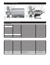
Sleeve
Washer
Lug
Top of foundation –
clean and wet down
Grout
Leveling wedges or shims – left in place
BaseGrout hole
(
1
/4")
Finished grouting
(
1
/2 to
3
/4")
Allowance
for leveling
Wood
frame
H min.
D
D
H min.
D D
1.5D
min.
3.0D
min.
H min.
D min.
2
16
15
14
13
12
11
10
9
8
7
6
5
4
3
2
1
H = Min. Submergence in feet
H
12345678910111213141516
V
V = Velocity in feet per second
= GPM x 0.321
Area
GPM x 0.4085
D
2
Figure 2 Figure 3