


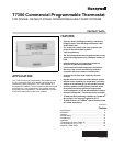

T7350 Commercial Programmable Thermostat
9 63-2605—06
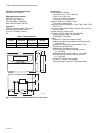
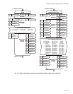
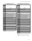
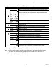
Table 5. T7350D Subbase for Three-stage Heat,
Three-stage Cool Systems.
a
Factory jumper between RC and RH for systems with one
transformer.
b
For changeover functional details, see Operation section.
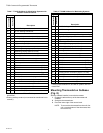
Table 6. T7350H Subbase for Three-stage Heat, Three-
stage Cool Systems with Network Communications
a
Factory jumper between RC and RH for systems with one
transformer.
b
Floating auxiliary contact (not connected to transformer hot or
common).
c
For changeover functional details, see Operation section.
Terminal
Description
Conventional
Heat Pump
RC
a
RC
a
24 VAC Cooling transformer.
RH
a
RH
a
24 VAC Heating transformer.
X X Common.
aux aux Auxiliary relay.
W1 O/B Conventional: Stage 1 heating relay.
Heat Pump: Changeover relay for heating (B) or
cooling (O)
b
.
W2 W1 Conventional: Stage 2 heating relay.
Heat Pump: 1st Stage auxiliary heat relay.
Y1 Y1 Conventional: Stage 1 cooling relay.
Heat Pump: Stage 1 compressor relay.
Y2 Y2 Conventional: Stage 2 cooling relay.
Heat Pump: Stage 2 compressor relay.
AS AS Discharge Air Sensor connection (1).
AS AS Discharge Air Sensor connection (2).
OS OS Outdoor Air Sensor connection (1).
OS OS Outdoor Air Sensor connection (2).
GGFan relay.
T3 T3 TR20 Series remote sensor connection (GND).
T4 T4 TR20 Series remote sensor connection (Sensor).
T5 T5 TR20 Series remote sensor connection (Set Pt).
T6 T6 TR20 Series remote sensor connection (Bypass).
T7 T7 TR20 Series remote sensor connection (LED).
W3 W2 Conventional: Stage 3 heat or stage 4 cool relay.
Heat Pump: 2nd Stage auxiliary heat relay.
Y3 — Conventional: Stage 3 cooling relay.
HS HS Humidity Sensor connection (signal: 0-10 Vdc).
HC HC Humidity Sensor connection (common).
HP HP Humidity Sensor connection (power).
M M Motion Sensor connection (1).
M M Motion Sensor connection (2).
Terminal
Description
Conventional
Heat Pump
RC
a
RC
a
24 VAC Cooling transformer.
RH
a
RH
a
24 VAC Heating transformer.
XXCommon.
aux
b
aux
b
Auxiliary relay connection (normally open).
aux
b
aux
b
Auxiliary relay connection (common).
W1 O/B Conventional: Stage 1 heating relay.
Heat Pump: Changeover relay for heating (B) or
cooling (O)
c
.
W2 W1 Conventional: Stage 2 heating relay.
Heat Pump: 1st Stage auxiliary heat relay.
Y1 Y1 Conventional: Stage 1 cooling relay.
Heat Pump: Stage 1 compressor relay.
Y2 Y2 Conventional: Stage 2 cooling relay.
Heat Pump: Stage 2 compressor relay.
AS AS Discharge Air Sensor connection (1).
AS AS Discharge Air Sensor connection (2).
OS OS Outdoor Air Sensor connection (1).
OS OS Outdoor Air Sensor connection (2).
G G Fan relay.
T3 T3 TR20 Series remote sensor connection (GND).
T4 T4 TR20 Series remote sensor connection (Sensor).
T5 T5 TR20 Series remote sensor connection (Set Pt).
T6 T6 TR20 Series remote sensor connection (Bypass).
T7 T7 TR20 Series remote sensor connection (LED).
W3 W2 Conventional: Stage 3 heat or stage 4 cool relay.
Heat Pump: 2nd Stage auxiliary heat relay.
Y3 — Conventional: Stage 3 cooling relay.
HS HS Humidity Sensor connection (signal: 0-10 Vdc).
HC HC Humidity Sensor connection (common).
HP HP Humidity Sensor connection (power).
M M Motion Sensor connection (1).
M M Motion Sensor connection (2).
ebus ebus LonWorks Bus (1).
ebus ebus LonWorks Bus (2).