


T7350 Commercial Programmable Thermostat
7 63-2605—06
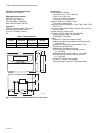
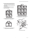
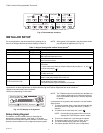
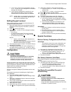
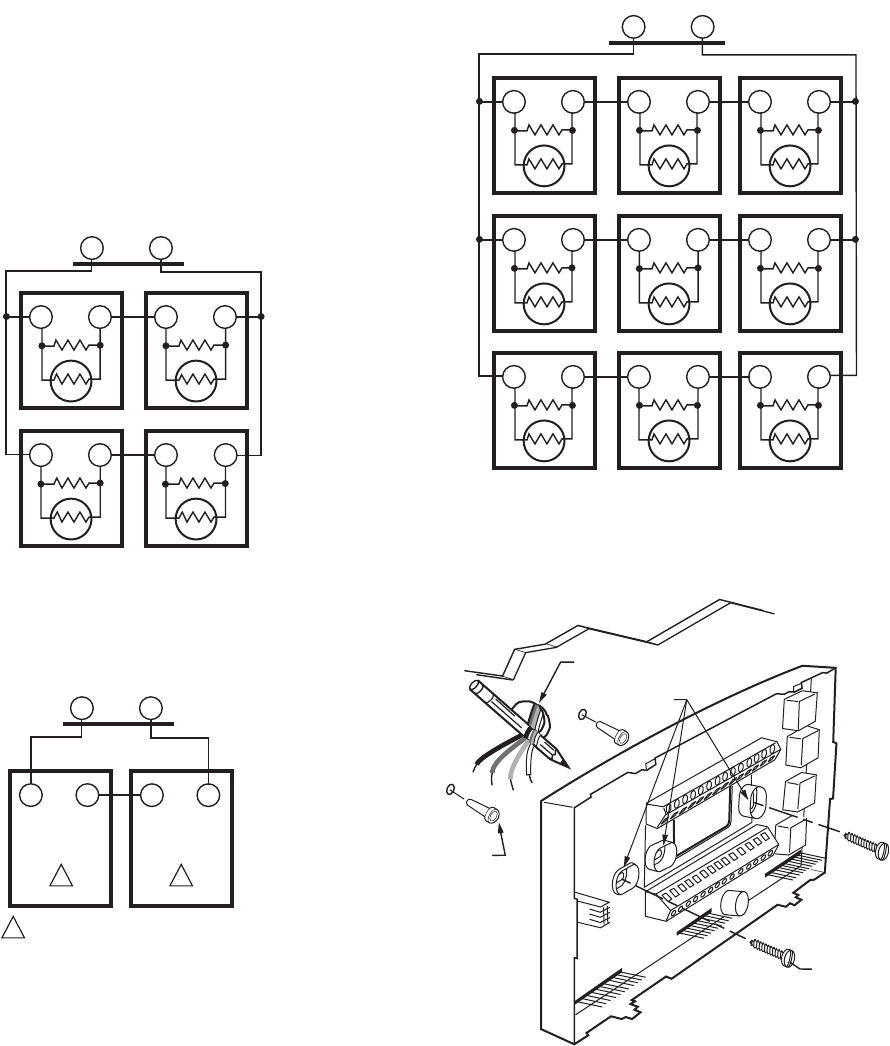
2. Use a pencil to mark the mounting holes. (See Fig. 7.)
3. Remove the subbase from the wall and drill two 3/16 in.
(4.76 mm) holes in the wall (if drywall) as marked. For
firmer material such as plaster or wood, drill two 7/32 in.
(5.56 mm) holes.
4. Gently tap anchors (provided) into the drilled holes until
flush with the wall.
5. Position the subbase over the holes, pulling wires
through the wiring opening.
6. Loosely insert the mounting screws into the holes.
7. Tighten mounting screws.
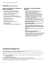
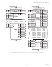
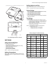
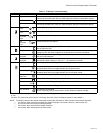
Fig. 4. Four TR21 Sensors providing a temperature
averaging network for T7350 Thermostat.
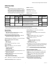
Fig. 5. Two TR-21A Sensors providing a temperature
averaging network for T7350 Thermostat.
Fig. 6. Nine TR21 Sensors providing a temperature
averaging network for T7350 Thermostat.
Fig. 7. Mounting the subbase.
M29184
T4 T3
TT
SUBBASE
TR21
TT
TR21
TT
TR21
TT
TR21
M29256
T4 T3
T7350 SUBBASE
TR21-A
T4 T3
TR21-A
T4 T3
1
1 1
THE TR21-A IS A 10K OHM SENSOR.
M29257
TT
TR21
TT
TR21
TT
TR21
TT
TR21
TT
TR21
TT
TR21
T
T
TR21
T
T
TR21
TT
TR21
T4 T3
SUBBASE
WIRES THROUGH WALL
WALL
ANCHORS
(2)
M19608
MOUNTING
HOLES
MOUNTING
SCREWS