


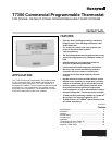
T7350 Commercial Programmable Thermostat
63-2605—06
6
INSTALLATION
When Installing this Product...
1. Read these instructions carefully. Failure to follow them
could damage the product or cause a hazardous
condition.
2. Check ratings given in instructions and on the product to
ensure the product is suitable for your application.
3. Installer must be a trained, experienced service
technician.
4. After installation is complete, check out product
operation as provided in these instructions.
CAUTION
Electrical Shock or Equipment Damage Hazard.
Can shock individuals or short equipment
circuitry.
Disconnect power supply before installation.
IMPORTANT
All wiring must agree with applicable codes,
ordinances and regulations.
MERCURY NOTICE
If this control is replacing a control that contains
mercury in a sealed tube, do not place your old
control in the trash. Dispose of properly.
Contact your local waste management authority for
instructions regarding recycling and the proper disposal
of an old control. If you have questions, call Honeywell
Customer Care Center at 1-800-468-1502.
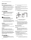
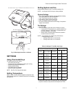
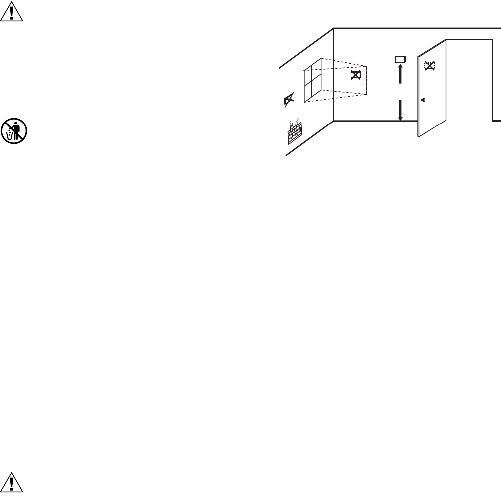
Location
Do not install the thermostat where it can be affected by:
— drafts, or dead spots behind doors and in corners.
— hot or cold air from ducts.
— radiant heat from sun or appliances.
— concealed pipes and chimneys.
— unheated (uncooled) areas such as an outside wall behind
the thermostat.
Subbase
WHEN USED TO SENSE ROOM TEMPERATURE
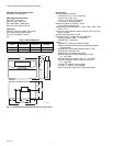
Install the thermostat about 5 ft (1.5m) above the floor in an
area with good air circulation at average temperature. (See
Fig. 3.)
WHEN NOT USED TO SENSE ROOM TEMPERATURE
When using the remote-mounted temperature (and humidity)
sensor(s) to sense ambient conditions, install the thermostat in
an area that is accessible for setting and adjusting the
temperature and settings.
CAUTION
Equipment Damage Hazard.
Can damage the TIM connection beyond repair.
Disconnect the TIM cable prior to opening or closing
the thermostat cover.
NOTE: Allow sufficient clearance below the thermostat to
plug in the TIM cable.
Install the remote-mounted sensor(s) about 5 ft (1.5m) above
the floor in an area with good air circulation at average
temperature. (See Fig. 3.)
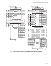
If multiple remote sensors are required, they must be arranged
in a temperature averaging network consisting of four or nine
sensors. (See Fig. 4 and 6.)
NOTE: Only TR20 models with neither setpoint adjustment
nor bypass can be used for temperature averaging.
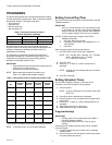
Fig. 3. Typical location of thermostat
or remote-mounted sensor.
IMPORTANT
To avoid electrical interference, which can cause
erratic performances, keep wiring runs as short as
possible and do not run thermostat wires adjacent to
the line voltage electrical distribution systems. Use
shielded cable (Belden type 8762 or equivalent for
2-wire). The cable shield must be grounded only at
the controlled equipment case.
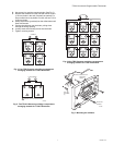
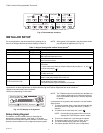
Mounting Subbase
The subbase mounts horizontally or vertically.
IMPORTANT
• When using the internal temperature sensor, the
device must be mounted horizontally (with the LCD
facing upwards). Precise leveling is not needed.
• When using remote sensors, thermostat mounting ori-
entation does not matter.
Wall mounting (using standard drywall screws) is standard.
Mounting to a 2 in.(50.8 mm) by 4 in. (101.6 mm) wiring box
can be accomplished:
— for a horizontal box, no extra hardware is required.
— for a vertical box, part 209651A is required.
— Mount to European standard wall box (having 60.3 mm
[2.4 in.] between mounting screws in a horizontal line) with
or without adaptive hardware.
1. Position and level the subbase.
NOTE: A level wallplate is only for appearance. The
thermostat functions properly when not level.
5 FEET
(1.5 METERS)
YES
NO
NO
NO
M4823A