


T7350 Commercial Programmable Thermostat
63-2605—06
8
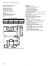
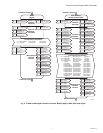
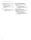
Wiring
CAUTION
Electrical Shock or Equipment Damage Hazard.
Can shock individuals or short equipment
circuitry.
Disconnect power supply before installation.
IMPORTANT
All wiring must comply with local electrical codes
and ordinances.
NOTE: Maximum (and recommended) wire size is
18-gauge (ø 1.02 mm). Do not use wire smaller than
22-gauge (ø 0.644 mm).
Follow equipment manufacturer wiring instructions when
available. Refer to the Wiring Diagram section for typical
hookups. A letter code is located near each terminal for
identification. Refer to Tables 3 through 8 for terminal
designations.
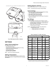
1. Loosen subbase terminal screws and connect system
wires.
2. Securely tighten each terminal screw.
3. Push excess wire back into the hole in the wall.
4. Plug the hole with nonflammable insulation to prevent
drafts from affecting the thermostat.
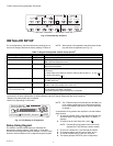
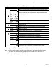
Table 3. T7350A Subbase for Single-stage Heat,
Single-stage Cool Systems.
a
Factory jumper between RC and RH for systems with one
transformer.
b
For changeover functional details, see Operation section.
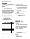
Table 4. T7350B Subbase for Two-stage Heat,
Two-stage Cool Systems.
a
Factory jumper between RC and RH for systems with one
transformer.
b
For changeover functional details, see Operation section.
Terminal
Description
Conventional
Heat Pump
RC
a
RC
a
24 VAC Cooling transformer.
RH
a
RH
a
24 VAC Heating transformer.
X X Common.
GGFan relay.
aux aux Conventional: Auxiliary relay or 2nd Stage of
heating or cooling relay.
Heat Pump: Auxiliary relay or 1st Stage auxiliary
heat relay.
W1 O/B Conventional: Stage 1 heating relay.
Heat Pump: Changeover relay for heating (B) or
cooling (O)
b
.
Y1 Y1 Conventional: Stage 1 cooling relay.
Heat Pump: Stage 1 compressor relay.
Terminal
Description
Conventional
Heat Pump
RC
a
RC
a
24 VAC Cooling transformer.
RH
a
RH
a
24 VAC Heating transformer.
X X Common.
aux aux Conventional: Auxiliary relay or 3rd stage of
heating or cooling.
Heat Pump: Auxiliary relay or 2nd stage auxiliary.
W1 O/B Conventional: Stage 1 heating relay.
Heat Pump: Changeover relay for heating (B) or
cooling (O)
b
.
W2 W1 Conventional: Stage 2 heating relay.
Heat Pump: 1st Stage auxiliary heat relay.
Y1 Y1 Conventional: Stage 1 cooling relay.
Heat Pump: Stage 1 compressor relay.
Y2 Y2 Conventional: Stage 2 cooling relay.
Heat Pump: Stage 2 compressor relay.
AS AS Discharge Air Sensor connection (1).
AS AS Discharge Air Sensor connection (2).
OS OS Outdoor Air Sensor connection (1).
OS OS Outdoor Air Sensor connection (2).
GGFan relay.
T3 T3 TR20 Series remote sensor connection (GND).
T4 T4 TR20 Series remote sensor connection (Sensor).
T5 T5 TR20 Series remote sensor connection (Set Pt).
T6 T6 TR20 Series remote sensor connection (Bypass).
T7 T7 TR20 Series remote sensor connection (LED).