


T7300F/Q7300H SERIES 2000 COMMERCIAL THERMOSTATS AND COMMUNICATING SUBBASES
9 63-4365
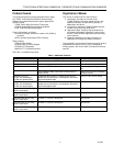
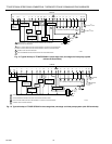
Table 2. Terminal descriptions and conditions.
Standard Terminal
Designations Typical Connection Function Terminal Type
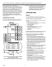
A1, A3 Damper control relay. See T7300F Installation Instructions, form
69-1025-3, installer setup 18, for control parameters.
Output Dry contract
A2 Dry auxiliary contact. (A2 is common to A1, A3.) Input —
AS,AS C7150B Discharge Air Sensor connection. Input —
B Heating changeover valve. Output 24V powered
contact
BM ML7984 Actuator connection. No call for heat; valve closed
during occupied periods and open during unoccupied periods.
Output —
C1, C2, C3, C4, C5 Communication input for T7147. Input/Output Low power
E Emergency heat relay. Output 24V powered
contact
EB, EB LonWorks® Bus connection to LonWorks® network. Input/output Communications
FC Fan control transformer. Input —
G Fan relay. Output —
GH High speed fan output. Activated during call for cooling. Output —
GL Low speed fan output. Activated on call for heat and fan On
selection.
Output —
O Cooling changeover valve. Output —
P1, P2 Pump interlock relay. Operates circulator pump in hydronic heat
or energizes conventional heat system.
Input, output —
R 24V system transformer. Input —
RC 24V cooling transformer. Input —
RH 24V heating transformer. Input —
RM ML7984 Actuator connection. No call for heat; valve closed. Call
for sta
g
e 1 heat; valve approximately one-half open. Call for
stage 2 heat; valve fully open.
Output —
T, T Remote sensor input for T7047 or T7147. Input —
W1 Stage 1 heating relay or auxiliary heat relay. Output —
W2 Stage 2 heating relay Output —
W3 Stage 3 heating relay Output —
X Heating transformer common. Input —
Y Cool call. 24V output on Y —
Y1 Stage 1 compressor contactor. Output —
Y2 Sta
g
e 2 coolin
g
compressor (conventional). Sta
g
e 2
compressor contactor (heat pump).
Output —
Y3 Stage 3 cooling compressor. Output —
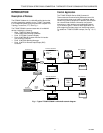
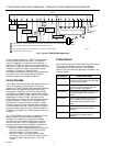
Communications
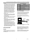
The Q7300H provides networking capability in a
LonWorks® system when using a Free Topology
Transceiver (FTT) transformer-coupled communications
port running at 78 kilobits per second (kbs). The
transformer-coupled communications interface offers a
much higher degree of common-mode noise rejection
while ensuring dc isolation.
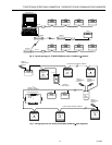
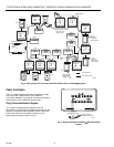
LonWorks® FTT networks are very flexible and convenient
to install and maintain, but it is imperative that the network
layout be carefully planned and accurate documentation
created and maintained. This aids in compliance
verification and future expansion of the network. It also
minimizes unknown or inaccurate wire run lengths, node-
to-node (device-to-device) distances, node counts, total
wire length, inaccurate repeater/router locations, and
misplaced or missing terminations. LonWorks® networks
can be configured in a variety of ways; refer to the E-Bus
FTT Network Wiring Guidelines, form 74-2865-1, for a
complete description of network topology rules and
maximum wire length. If longer runs are required, add a
Q7740A 2-way or Q7740B 4-way repeater to extend the
LonWorks® Bus length. Add a Q7751A to partition the
system into two segments to double the length of
LonWorks® Bus.