


T7300F/Q7300H SERIES 2000 COMMERCIAL THERMOSTATS AND COMMUNICATING SUBBASES
15 63-4365
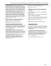
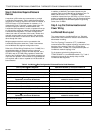
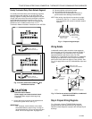
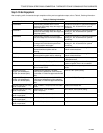
Doubly Terminated Daisy-Chain Network Segment
In a doubly terminated daisy-chained topology segment,
two terminations are required, one at each end of the
topology segment. Doubly terminated segments use the
orange and brown wires. Mount the termination modules
on the appropriate terminals as shown in Fig. 10. For
additional wiring information, refer to the E-Bus Wiring
Guidelines, form 74-2865, and the Excel 10 FTT
Termination Module Installation Instructions, form 95-7554.
C1 C2 C3 C4 C5
EB EB
XTTASAS
C1 C2 C3 C4 C5
EB EB
XTTASAS
ORANGEBROWN
YELLOW
PART NO. 209541B
TERMINATION MODULE
ORANGEBROWN
YELLOW
PART NO. 209541B
TERMINATION MODULE
M16122
Fig. 10. Doubly terminated LonWorks Bus
termination modules.
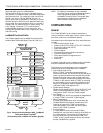
CAUTION
Electrical Shock Hazard.
Power supply can cause electrical shock.
Disconnect power supply before beginning
installation.
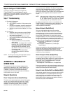
1.
Loosen the terminal screws on the subbase and
connect the system wires. See Fig. 11.
IMPORTANT
Use 18-gauge, solid-conductor color-coded
thermostat cable for proper wiring. If using 18-
gauge stranded wire, do not use more than two
wires. Do not use larger than 18-gauge wire.
2.
Securely tighten each terminal screw.
3.
Push excess wire back into the hole.
4.
Plug the hole with nonflammable insulation to
prevent drafts from affecting the thermostat.
NOTE: After wiring, check that all connections are tight
and secure. See Fig. 11. Loose or intermittent
wire connections can cause inconsistent system
operation.
M4826
FOR WRAPAROUND
INSERTION STRIP
7/16 IN. (11 MM).
FOR STRAIGHT
INSERTION STRIP
5/16 IN. (8 MM).
Fig. 11. Proper wiring technique.
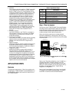
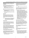
Wiring Details
LonWorks® network cable should be wired separately
from the power and I/O wires when installing Q7300s. If
this is not possible, use a minimum of 4 in. (102 mm)
separation between split ferrite cores (Fair-Rite
0443164151, or equivalent Honeywell part no. 229997CB,
containing five split ferrite cores) to ensure compliance
with Class B limits (does not apply to Class A limits). See
Fig. 12. to apply ferrite cores to LonWorks® Bus input and
output.
M10886A
WIRES TO Q7300H
COMMUNICATING SUBBASE
WIRES TO Q7300H
COMMUNICATING SUBBASE
WIRES TO ALL
INPUTS AND
OUTPUTS
WIRES TO ALL
INPUTS AND
OUTPUTS
1.
2.
Fig. 12. Ferrite core wires from Q7300H to LonWorks®
inputs and outputs.
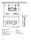
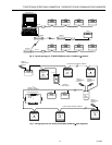
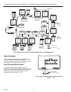
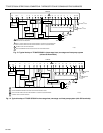
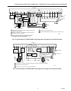
Step 4. Prepare Wiring Diagrams
Fig. 13 through 16 show T7300F/Q7300H terminal
arrangements and provide detailed wiring diagrams.
Reference these diagrams to prepare the site-specific job
drawings.