


T7300F/Q7300H SERIES 2000 COMMERCIAL THERMOSTATS AND COMMUNICATING SUBBASES
63-4365 2
LIST OF FIGURES
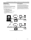
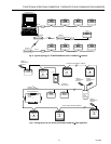
Fig. 1. Typical T7300F/Q7300H LonWorks® network diagram.......................... 3
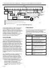
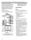
Fig. 2. Typical T7300F/Q7300H application....................................................... 4
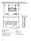
Fig. 3. T7300F/Q7300H dimensions in in. (mm). ............................................... 8
Fig. 4. Functional Profile Number 8060
LonMark® Thermostat Object
(Type 09) (Thermostat profile variables not used are grayed). ..................... 10
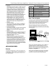
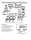
Fig. 5. Connecting personal computer to LonWorks® Bus................................ 11
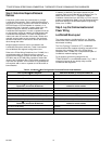
Fig. 6. Typical topology for T7300F/Q7300H devices in
LonWorks® network..................................................................................... 13
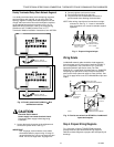
Fig. 7. Wiring layout for two doubly terminated LonWorks® Bus segments...... 13
Fig. 8. Wiring layout for one doubly terminated daisy-chain
LonWorks® Bus segment. ............................................................................ 14
Fig. 9. Singly terminated LonWorks
Bus termination module. ........................ 14
Fig. 10. Doubly terminated LonWorks® Bus termination modules. ................... 15
Fig. 11. Proper wiring technique. ....................................................................... 15
Fig. 12. Ferrite core wires from Q7300H to digital inputs and outputs............... 15
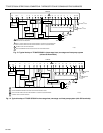
Fig. 13. Typical hookup of T7300F/Q7300H in three-stage heat,
two-stage cool heat pump system................................................................. 16
Fig. 14. Typical hookup of T7300F/Q7300H in three-stage heat,
two-stage cool heat pump system................................................................. 16
Fig. 15. Typical hookup of T7300F/Q7300H in three-stage heat,
three-stage cool conventional system........................................................... 17
Fig. 16. Typical hookup of T7300F/Q7300H in two-stage heat,
one-stage cool conventional system. ............................................................ 17
LIST OF TABLES
Table 1. Additional Products. ............................................................................. 5
Table 2. Terminal descriptions and conditions................................................... 9
Table 3. Application Steps. ................................................................................ 11
Table 4. LonWorks® Configuration Rules and Device Node Numbers.............. 12
Table 5. Field Wiring Reference Table ............................................................... 18
Table 6. Ordering Information. ........................................................................... 19