


T7300F/Q7300H SERIES 2000 COMMERCIAL THERMOSTATS AND COMMUNICATING SUBBASES
63-4365 20
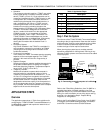
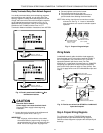
Step 6. Configure T7300F/Q7300H
Use Excel LonSpec™ Software to configure the
T7300F/Q7300H Thermostat/Subbase for specific
applications. The Excel LonSpec™ User’s Guide, form 74-
2937, provides software operation instructions for the
personal computer.
Step 7. Troubleshooting
1.
Check for 24 Vac power.
a. Turn on power.
b. Use a meter to check for 24 Vac power at the
subbase.
c. If 24 Vac is not present, check the transformer
for secure connections and proper operation.
d. If 24 Vac is present at the subbase, turn off the
power.
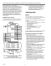
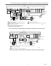
2.
Check wiring.
a. Inspect all wiring connections at the Q7300H
terminals and verify compliance with the job
site engineering drawings.
b. If any wiring changes are required,
first
be
sure to remove power from the device
before
starting work.
c. Pay particular attention to:
Terminal connections. Connect GND to
earth ground.
Device Wiring. In hookups with A1 and A2
terminals, use A1 and A2 when contacts
are normally closed in Occupied mode. In
hookups with A2, A3 terminals, use A2
and A3 when contacts are normally open
in Occupied mode.
O/B Terminals. The Q7300H2003
provides O/B terminals for cool/heat
changeover.
NOTE: All wiring must comply with applicable electrical
codes and ordinances or as specified in
installation wiring diagrams.
APPENDIX A: SEQUENCE OF
OPERATIONS
This appendix provides the network related control
sequences of operation for the T7300F/Q7300H. For
temperature control related sequences, refer to the
T7200D,E, T7300D,E,F and Q7300 Series 2000
Programmable Commercial Thermostat and Subbase
Product Data, form no. 63-4355.
Network Operations
Room Temperature Sensor (DestRmTemp)
This is the room space temperature sensor. This sensor
can be local (contained internally within the T7300F),
remote (external but hard-wired back to the Q7300H
subbase), or network (physical sensor is located
elsewhere on the LonWorks
Bus, and its value is
communicated to the Q7300H). The Room Temperature
sensor provides the temperature input for the temperature
control loop of the T7300F. If both local and remote
sensors are available, the two values can be
averaged
and
the resulting value supplied to the temperature control
routine.
NOTE: A physical sensor (either local or remote)
cannot
be averaged with a network sensor. A valid value
for the network sensor input gives the network
sensor priority over any locally-wired sensors.
If a valid room temperature value is not available to the
T7300F/Q7300H, the temperature control algorithm in the
T7300F is disabled, causing the heating and cooling
control outputs to be turned off.
Network Setpoint (DestSetPoint)
This is a center-setpoint signal sent from another
LonWorks
Bus device. When received, it is used to
calculate the actual cooling or heating occupied setpoint.
The DestSetPoint value becomes the center of the Zero
Energy Band (ZEB) between the cooling and heating
occupied setpoints. The size of the ZEB is found by taking
the difference between the programmed heating and
cooling occupied setpoints (CoolOccSpt and HeatOccSpt);
therefore, the actual setpoints are found as follows:
ActualCoolSpt = DestSetPoint + (CoolOccSpt -
HeatOccSpt) / 2
ActualHeatSpt = DestSetPoint - (CoolOccSpt -
HeatOccSpt) / 2
During unoccupied times, the network setpoint value is not
referenced, and the programmed setpoints are used
instead (CoolUnoccSpt and HeatUnoccSpt). During
occupied times, if DestSetPoint is valid, it will be used to
override any internal setpoints.
Network Setpoint Offset (DestSptOffset)
This is a setpoint adjustment signal sent from another
LonWorks
device. When received, it is used to
bump
the
current setpoint value up or down. The amount of the
bump is the value of DestSptOffset itself. The actual
setpoints are found as follows:
ActualSetpoint = CurrentSetPoint + DestSptOffset
During unoccupied times, the network setpoint offset value
is not referenced, and the programmed setpoints are used
instead (CoolUnoccSpt and HeatUnoccSpt).
Setpoint Limits (MinCoolSetPt and MaxHeatSetPt)
User-entered setpoint limits are provided by MinCoolSetPt
and MaxHeatSetPt. The occupied setpoints used in the
control algorithms are limited by these parameters. The
lowest actual setpoint allowed in cool mode is equal to
MinCoolSetPt, and the highest actual setpoint allowed in
heat mode is equal to MaxHeatSetPt.