


– 7 –
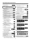
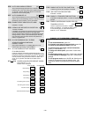
*80 *81 SYSTEM NON-ALARM CODES
Enter 00-09; B-F (11-15).
Default = 00 for all reports
*80 1st Digit *81 2nd Digit
Close
|
|
Open
|
|
Low Battery
|
|
Low Battery Restore
|
|
AC Loss
|
|
AC Restore
|
|
Test
|
|
Power Up
|
|
Cancel
|
|
Program Tamper
|
|
*83 FIRST TEST REPORT TIME | | |
[Day 00; hour 12; min 00] Days 01-07 Hours 00-23 Min 00-
59; 00 in all boxes = instant (Day 01= Monday)
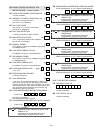
*84 SWINGER SUPPRESSION [01] |
01-15 alarms
Must be "00" (disabled) for UL.
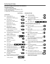
*85 ENABLE DIALER REPORTS FOR PANICS & DURESS
1=enable; [0=disable]
995
996
999
Duress
*87 ENTRY WARNING [1]
1=continuous; 0=3 beeps
*88 BURG. ALARM COMM. DELAY [0]
1=16 seconds; 0=no delay
Must be "0" for UL installations.
*89 RESTORE REPORT TIMING [0]
0=Instant; 1=After bell timeout if zone is restored; 2=when
system is disarmed. Must be "0" for UL installations.
*90 SEC. SUBS. ACCT # | | | |
Enter 00-09; B-F (11-15) [15 15 15 15]
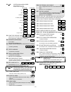
2nd Page Programming Fields (press *94)
1*01 1*09 ASSIGN RESPONSE TYPE FOR ZONES.
Skip these fields. Use #93 Menu Mode, Zone
Programming to program the response types.
1*17 LOBBY PARTITION [0]
Enter the "common lobby" partition (1-8)
1*18 AFFECTS LOBBY [0]
Enter 1 if this partition affects the common lobby; enter 0 if it
does not.
Must be "0" for UL installations.
1*19 ARMS LOBBY [0]
Enter 1 if arming this partition attempts to arm lobby; enter 0
if it does not.
Must be "0" for UL installations.
1*20 EXIT ERROR LOGIC ENABLE [0]
0=No; 1=Bypass E/E and Interior zones faulted after exit
delay.
Must be "0" for UL installations.
1*21 EXIT DELAY RESET [0]
0=No; 1=Resets Exit Delay to programmed value after zone
is closed and then faulted prior to end of exit delay.
Must be "0" for UL installations.
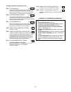
FIELDS 1✳22-1✳25: Allow four sets of two zones each to be
linked so that both must fault within a five minute period to
cause an alarm. Default for these fields = [000], [000].
1*22 CROSS-ZONING PAIR ONE
| |
1*23 CROSS-ZONING PAIR TWO
| |
1*24 CROSS-ZONING PAIR THREE
| |
1*25 CROSS-ZONING PAIR FOUR
| |
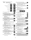
MISCELLANEOUS WIRELESS OPTIONS
Fields 1*28 - 1*31 are not applicable for UL installations.
1*28 RF TX LOW BATTERY SOUND [0]
1=immediate; 0=when disarmed
1*29 RF TX LOW BATTERY REPORTING [0]
1=enable; 0=disable
1*30 RF RCVR CHECK-IN INTERVAL [06] |
02-15 times 2 hours; 00 disables supervision
1*31 RF XMITTER CHECK-IN INTERVAL [12] |
02-15 times 2 hours; 00 disables transmitter supervision
1*33 TOUCHTONE W/ROTARY BACKUP [0]
1=enable; 0=disable
1*34 COMM. SPLIT REPORTING [0]
0=no; 1=alarms and alarm restores primary, others secondary;
2=open/close, test secondary, others primary. See
51 for
comments if using with dual reporting.
1*35 1*38 ALARM REPORT CODES & ID DIGITS FOR
ZONES 65-80.
Skip these fields. Use #93 Menu Mode, Zone
Programming to program the report codes.
1*39 SUPERVISORY AND RESTORE CODES FOR
ZONES 65-80.
Enter 00-09; B-F (11-15).
Default = [00 00 00 00 00]
|
Alarm Rst
|
Trbl
|
Trbl Rst
|
Byp
|
Byp Rst