


– 26 –
Relay Devices Programming
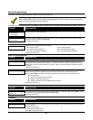
From Data Field Programming Mode, press #93 to display the "ZONE PROG?" prompt. Press [0] (NO) to each menu option
until the "RELAY PGM?" prompt appears. Press [1] (YES).
While in this mode, press [✱] to advance to next screen. Press [#] to back up to the previous screen.
PROMPT
EXPLANATION
ENTER RELAY #
(00=QUIT) 01
Enter the relay (output device) identification number 01-16. This is a reference number only, used for
identification purposes. The actual module address and relay number on the module are programmed in the
last two prompts.
Press [✱] to continue.
02 A EV ZL ZT P
STT 0 0 00 00 0
Press [✱] to continue.
02 A ZL ZT P
STOP 0 00 00 0
The keypad displays a summary STOP screen.
Press [✱] to continue.
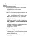
02 RELAY ACTION
NO RESPONSE 0
The Relay Action is the way in which the relay will respond when activated by the "start" event. Enter the
desired action for this relay as follows:
0=not used; 1=close for 2 secs.; 2=stay closed; 3=pulse on/off
02 START EVENT
NOT USED 0
An output may be activated by an Event/Zone List combination, and/or by a Zone Type/System Operation.
For an Event/Zone List combination, enter the event code as follows:
0=not used; 1=alarm; 2=fault; 3=trouble
If you are not using a Zone List to activate the relay, enter 0.
Press [✱] to continue.
02 START: ZN LIST
0
A zone list is a set of zones that can be used to initiate the start or stop relay action. If a zone list is being
used to start this relay action, enter the zone list number, 1-8. If a zone list is not being used, enter 0.
Press [✱] to continue.
02 START: ZN TYPE
NO RESPONSE 00
A Zone Type/System Operation can be used instead of or in addition to an Event/Zone List combination or
a specific zone to start the relay action. If a Zone Type/System Operation is being used, enter the 2-digit
code as listed in the table that follows.
Press [✱] to continue.
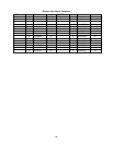
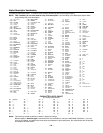
Choices for Start/Stop Zone Types and System Operations:
00 = No Response (Not Used) 23 = No Alarm Response 43 = Communication failure
01 = Entry/Exit #1 31 = End of Exit Time 44 = RF Low Battery
02 = Entry/exit #2 32 = Start of Entry Time 45 = Polling Loop Failure
03 = Perimeter 33 = Any Burglary Alarm 51 = RF Receiver Failure
04 = Interior Follower 34 = Code + [#] + 71 Key Entry 52 = Kissoff
05 = Trouble Day/Alarm Night 35 = Code + [#] + 72 Key Entry 54 = Fire Zone Reset
06 = 24-Hr. Silent 36 = At Bell Timeout ** 55 = Disarm + 1 Minute
07 = 24-Hr. Audible 37 = 2 Times Bell Timeout ** 56 = XX Minutes (enter XX in field 1*74) *
08 = 24-Hr. Auxiliary 38 = Chime 57 = YY Seconds (enter YY in field 1*75) *
09 = Fire Alarm or Trouble 39 = Fire Alarm 58 = Duress
10 = Interior W/Delay 40 = Bypassing
20 = Arming-STAY*** 41 = AC Power Fail
21 = Arming-AWAY**** 42 = System Battery Low
60 = Audio Alarm Verification (must be
selected for both START and STOP
operation)
22 = Disarming (Code + Off)
* Stop condition only
** Or at disarming, whichever occurs earlier
*** The output also activates when the partition is armed in the INSTANT mode
**** The output also activates when the partition is armed in the MAXIMUM mode
If you are using options 56 and/or 57 (usually as the STOP Zone Type), you must program data fields 1*74
and 1*75 for the respective relay timeouts for minutes and seconds.