


INSTALLATION INSTRUCTIONS 3-phase R-410A Split System Heat Pump
506 01 5102 00 9
ELECTRICAL WIRING
!
WARNING
ELECTRICAL SHOCK HAZARD
Failure to follow this warning could result in per‐
sonal injury or death.
Before installing, modifying or servicing system,
turn OFF the main (remote) electrical disconnect
device. There may be more than one disconnect
device.
Refer to unit rating plate for the required supply voltage.
Depending on the model, required supply voltage will be:
208/230 V, 3-phase, 60 Hz.
or
460 V, 3-phase, 60 Hz.
Outdoor units are approved for use with copper
conductors only. Do not use aluminum wire.
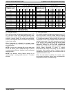
Refer to unit rating plate for minimum circuit ampacity and
circuit protection requirements.
Grounding
Permanently ground unit in accordance with the National
Electrical Code and local codes or ordinances. Use a
copper conductor of the correct size from the grounding
lug in control box to a grounded connection in the service
panel or a properly driven and electrically grounded
ground rod.
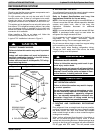
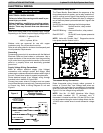
Supply Voltage Wiring Connections
Make all outdoor electrical supply (Line Voltage)
connections with raintight conduit and fittings. Most
codes require a disconnect switch outdoors within sight of
the unit. Consult local codes for special requirements.
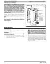
Route electrical supply (Line Voltage) wiring through
knockout hole in bottom of Control Box.
Connect two power wires to Contactor and one power
wire to Blue lead wire (use wire nut). Connect ground wire
to Ground Lug. Refer to Wiring Diagram on unit and
Figure 9.
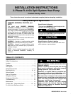
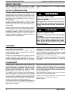
Figure 9
208/230 V and 460 V
Electrical Supply
(Line Voltage) Connections
DISCONNECT
PER NEC AND/OR
LOCAL CODES
CONTACTOR
GROUND
LUG
FIELD GROUND
WIRING
FIELD POWER
WIRING
11
13
L1
L3
L2
BLUE LEAD WIRE
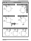
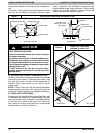
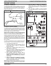
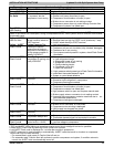
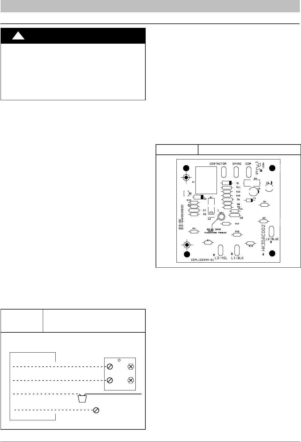
Phase Monitor Relay Board
The Phase Monitor Board detects the sequence of the
three phase electrical system, and a relay breaks the Y
(call for cooling) control signal if the phasing is incorrect.
Additionally, the board will detect the loss of voltage on
any of the three phase inputs and break the Y signal in the
same way.
An LED on the board displays the following status:
Red LED ON - Normal function, relay contact
closed.
Red LED Blinking - Abnormal function, relay contact
open.
Red LED OFF - No 24 VAC control power present at
board.
NOTE: Units with Comfort Alertt Diagnostics device
have phase monitor feature built in.
Figure 10 Phase Monitor Relay Board
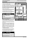
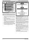
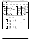
Thermostat Wiring Connections
Route thermostat wiring through rubber grommet in
bottom of Control Box. Low voltage lead wires are
provided in the control box for connection to thermostat
wires (use wire nuts). Refer to Wiring Diagram on unit and
Figure 11 for low voltage wiring examples.
NOTE: Use No. 18 AWG (American Wire Gage)
color-coded, insulated (35 °C minimum) wire. If
thermostat is located more than 100 feet (30.5 m) from
unit as measured along the control voltage wires, use No.
16 AWG color-coded wires to avoid excessive voltage
drop.