


INSTALLATION INSTRUCTIONS 3-phase R-410A Split System Heat Pump
506 01 5102 00 5
REFRIGERATION SYSTEM
A. COMPONENT MATCHES
Check to see that the proper system components are in
place, especially the indoor coil.
R-410A outdoor units can only be used with R-410A
specific indoor coils. If there is a refrigerant mis-match,
consult the indoor coil manufacturer to determine if a
refrigerant conversion kit is available for the indoor coil.
This outdoor unit is designed for use only with indoor coils
that utilize a TXV refrigerant metering device. If any other
type of metering device is installed on the indoor coil,
consult the indoor coil manufacturer to determine if a TXV
conversion kit is available.
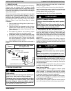
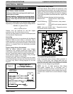
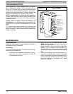
When installing a TXV on an indoor coil, follow the
instructions provided with the new TXV.
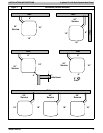
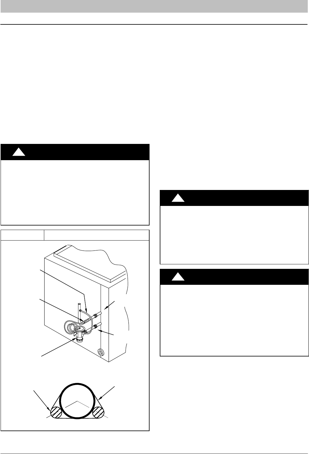
A typical TXV installation is shown in Figure 3.
!
CAUTION
PRODUCT DAMAGE HAZARD
Failure to follow this caution may result in product
damage.
Indoor coil and outdoor unit must be listed as a
certified combination (match) in the ARI Unitary
Directory of Certified Products.
Indoor coil must have R-410A specific, TXV refrig‐
erant metering device.
Figure 3 Typical TXV Installation
TXV
SENSING
BULB
EQUALIZER
TUBE
8 O'CLOCK 4 O'CLOCK
STRAP
SENSING BULB
(EITHER SIDE)
SUCTION
TUBE
INDOOR
COIL
SUCTION
TUBE
LIQUID
TUBE
B. REFRIGERANT LINE SETS
The refrigerant line set must be properly sized to assure
maximum efficiency and proper oil circulation.
Refer to Product Specifications and Long Line
Applications Guideline for line set sizing.
NOTE: If the line set actual length is to exceed 80 feet, or
if there is more than 20 feet vertical separation between
outdoor and indoor units, refer to the Long Line
Application Guideline document for additional
instructions.
NOTE: Line set actual length must not exceed 200 feet.
NOTE: A crankcase heater must be used when the
refrigerant line length exceeds 80 feet.
If it is necessary to add refrigerant line in the field, use
dehydrated or dry, sealed, deoxidized, copper
refrigeration tubing. Do not use copper water pipe.
Do not remove rubber plugs or caps from copper tubing
until connections are ready to be made.
Be extra careful when bending refrigeration tubing.
Tubing can “kink” easily, and if this occurs, the entire
length of tubing must be replaced.
!
WARNING
PERSONAL INJURY HAZARD
Failure to follow this warning could result in per‐
sonal injury and/or death.
Relieve pressure and recover all refrigerant before
servicing existing equipment, and before final unit
disposal. Use all service ports and open all flow-
control devices, including solenoid valves.
!
CAUTION
UNIT OPERATION HAZARD
Failure to follow this caution may result in improp‐
er product operation.
Do not leave system open to atmosphere any lon‐
ger than absolutely required for installation. Inter‐
nal system components - especially refrigerant
oils - are extremely susceptible to moisture con‐
tamination. Keep ends of tubing sealed during
installation until the last possible moment.
C. ROUTING AND SUSPENDING REFRIGERANT
LINES
Run refrigerant lines as straight and direct as possible,
avoiding unnecessary bends and turns. Always insulate
the entire suction line. Both lines should be insulated
when routed through an attic or when routed through an
underground raceway.
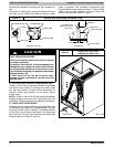
When routing refrigerant lines through a foundation or
wall, do not allow refrigerant lines to come in direct
contact with the building structure. Make openings large
enough so that lines can be wrapped with extra insulation.
Fill all gaps with RTV caulk. This will prevent noise