


INSTALLATION INSTRUCTIONS 3-phase R-410A Split System Heat Pump
16 506 01 5102 00
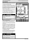
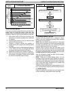
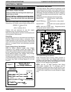
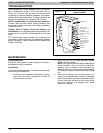
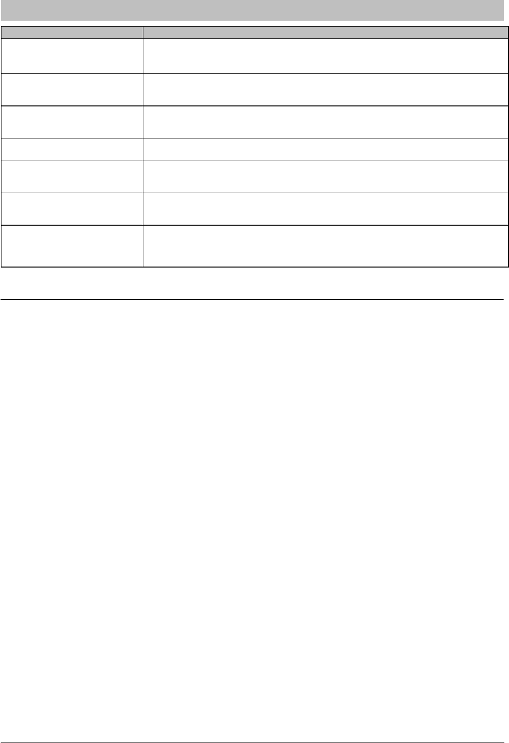
Figure 17 Comfort Alertt Diagnostics (some models)
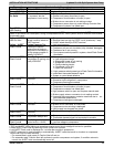
Miswired Module Indication Troubleshooting Information
Green LED is not on, module
does not power up
Determine if both R and C module terminals are connected. Verify voltage is
present at module's R and C terminals.
Green LED intermittent, mod‐
ule powers up only when com‐
pressor runs
Determine if R and Y terminals are wired in reverse. Verify module's R and C ter‐
minals have a constant source.
TRIP LED is on but system
and compressor check OK
Verify Y terminal is wired properly per OEM wiring diagram. Verify voltage at con‐
tactor coil falls below 0.5VAC when off. Verify 24VAC is present across Y and C
when thermostat demand signal is present. If not, R and C are reverse wired.
TRIP LED and ALERT LED
flashing together
Verify R and C terminals are supplied with 19-28VAC.
ALERT Flash Code 3
(Compressor short cycling)
displayed incorrectly
Verify Y terminal is connected to 24VAC at contactor coil. Verify voltage at
contactor coil falls below 0.5VAC when off.
ALERT Flash Code 5 or 6
(Open Circuit, Missing Phase)
displayed incorrectly
Check that compressor T1 and T3 wires are through module's current sensing
holes. Verify Y terminal is connected to 24VAC at contactor coil. Verify voltage at
contactor coil falls below 0.5VAC when off.
ALERT Flash Code 8
(Welded Contactor) displayed
incorrectly
Determine if module's Y terminal is connected. Verify Y terminal is connected to
24VAC at contactor coil. Verify 24VAC is present across Y and C when ther‐
mostat demand signal is present. If not, R and C are reversed wired. Verify
voltage at contactor coil falls below 0.5VAC when off. Review.
R-410A QUICK REFERENCE GUIDE
• R-410A refrigerant operates at 50% - 70% higher pressures than R-22. Be sure that servicing equipment and
replacement components are designed to operate with R-410A.
• R-410A refrigerant cylinders are rose colored.
• Recovery cylinder service pressure rating must be 400 psig, DOT 4BA400 or DOT BW400.
• R-410A systems should be charged with liquid refrigerant. Use a commercial type metering device in the manifold hose.
• Manifold sets should be 750 psig high-side and 200 psig low-side with 520 psig low-side retard.
• Use hoses with 750 psig service pressure rating.
• Leak detectors should be designed to detect HFC refrigerant.
• R-410A, as with other HFC refrigerants, is only compatible with POE oils.
• POE oils absorb moisture rapidly. Do not expose oil to atmosphere.
• POE oils may cause damage to certain plastics and roofing materials.
• Vacuum pumps will not remove moisture from oil.
• A liquid line filter-drier is required on every unit.
• Do not use liquid line filter-driers with rated working pressures less than 600 psig.
• Do not install a suction line filter-drier in liquid line.
• Wrap all filter-driers and service valves with wet cloth when brazing.
• Do not use with an R-22 TXV.
• If indoor unit is equipped with an R-22 TXV, it must be changed to an R-410A TXV.
• Do not use capillary tube indoor coils.
• Never open system to atmosphere while it is under a vacuum.
• When system must be opened for service, break vacuum with dry nitrogen and replace all filter-driers.
• Do not vent R-410A into the atmosphere.
• Observe all WARNINGS, CAUTIONS, NOTES, and bold text.
International Comfort Products, LLC
Lewisburg, TN 37091
International Comfort Products, LLC
Lewisburg, TN 37091