


INSTALLATION INSTRUCTIONS 3-phase R-410A Split System Heat Pump
506 01 5102 00 15
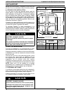
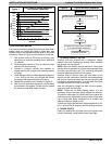
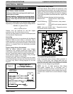
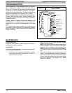
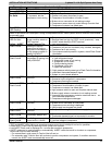
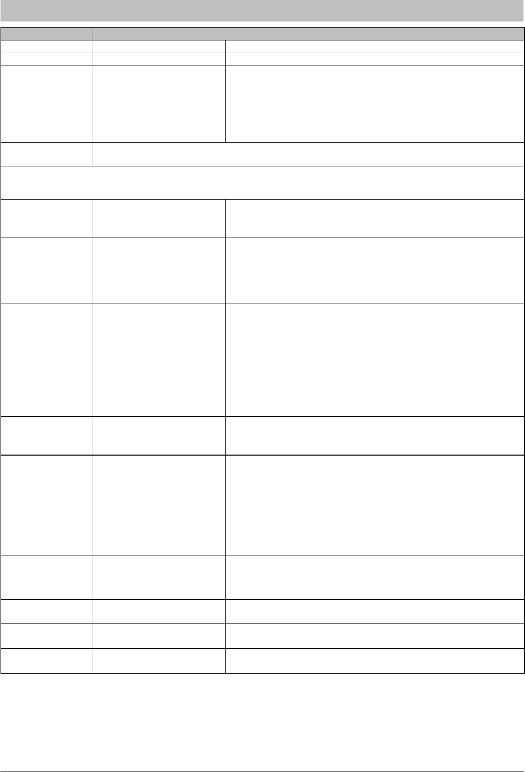
Figure 16 Comfort Alertt Diagnostics (some models)
Status LED Status LED Description Status LED Troubleshooting Information
Green “POWER” Module has power Supply voltage is present at module terminals
Red “TRIP” LED
On Solid
Thermostat demand signal
Y1 is present, but the
compressor is not running
1. Compressor protector is open
2. Outdoor unit power disconnect is open
3. Compressor circuit breaker or fuse(s) is open
4. Broken wire or connector is not making contact
5. Compressor power wires not routed through Comfort Alert
6. Compressor contactor has failed open
Red “TRIP”
LED Flashing
The anti-short cycle timer (3 minutes), in module is preventing compressor restart.
Module locks out compressor when compressor damaging ALERT codes appear. Lockout ALERT codes are
noted in the Status LED Description; during a compressor lockout, 24VAC power must be removed from module
to manually reset.
Yellow “ALERT”
LED On Solid
A short circuit or over
current condition exists on
PROT terminal
1. Compressor contact coil shorted
2. Electrical load too high for PROT circuit (maximum) 1 amp
3. 24 VAC wired directly to PROT terminal
Yellow “ALERT”
Flash Code 2
System Pressure Trip
Discharge or suction
pressure out of limits or
compressor overloaded (if
no high pressure switch in
system) LOCKOUT
1. High head pressure
2. Condenser coil poor air circulation (dirty, blocked, damaged)
3. Condenser fan is not running
4. If low pressure switch present in system, check Flash Code 3
information
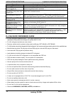
Yellow “ALERT”
Flash Code 3
Short Cycling
Compressor is running only
briefly LOCKOUT
1. If low pressure switch is open:
a. Low refrigerant charge
b. Evaporator bower is not running
c. Evaporator coil is frozen
d. Faulty metering device
e. Condenser coil is dirty
f. Liquid line restriction
2. If high pressure switch present go to Flash Code 2 information
3. Intermittent thermostat demand signal
4. System or control board defective
Yellow “ALERT”
Flash Code 4
Locked Rotor
LOCKOUT
1. Low line voltage to compressor
2. Excessive liquid refrigerant in compressor
3. Compressor bearings are seized
Yellow “ALERT”
Flash Code 5
Open Circuit 1. Outdoor unit power disconnect is open
2. Compressor circuit breaker or fuse(s) is open
3. Compressor contactor has failed open
4. High pressure switch is open and requires manual reset
5. Broken supply wires or connector is not making contact
6. Unusually long compressor protector reset time due to ex‐
treme ambient temperature
7. Compressor windings are damaged
Yellow “ALERT”
Flash Code 6
Missing Phase
LOCKOUT
1. Compressor fuse is open on one phase
2. Broken wire or connector on one phase
3. Compressor motor winding is damaged
4. Utility supply has dropped one phase
Yellow “ALERT”
Flash Code 7
Reverse Phase
LOCKOUT
1. Compressor running backward do to supply phase reversal
Yellow “ALERT”
Flash Code 8
Welded Contactor
Compressor always runs
1. Compressor contactor has failed closed
2. Thermostat demand signal not connected to module
Yellow “ALERT”
Flash Code 9
Low Voltage
Control circuit < 18VAC
1. Control circuit transformer is overloaded
2. Low line voltage to compressor
S Flash Code number corresponds to a number of LED flashes, followed by a pause and then repeated.
S TRIP and ALERT LEDs flashing at same time means control circuit voltage is too low for operation.
S Reset ALERT Flash code by removing 24VAC power from module.
S Last ALERT Flash code is displayed for 1 minute after module is powered on.
S ALERT codes can be reset manually or automatically. ALERT codes that result in a lockout or compressor
lockout can only be reset manually.
- For manual reset, cycle power to Comfort Alert off and on.
- For automatic reset, Comfort Alert will continue to monitor compressor and system; if condition returns to
normal, the ALERT code is automatically turned off.