


INSTALLATION INSTRUCTIONS 3-phase R-410A Split System Heat Pump
2 506 01 5102 00
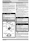
INSPECT NEW UNIT
After uncrating unit, inspect thoroughly for hidden
damage. If damage is found, notify the transportation
company immediately and file a concealed damage
claim.
SAFETY CONSIDERATIONS
Consult a qualified installer, service agency, or the
dealer/distributor for information and assistance. The
qualified installer must use factory authorized kits and
accessories when modifying this product. Refer to the
individual instructions packaged with the kit or accessory
when installing.
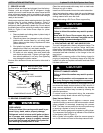
The weight of the product requires careful and proper
handling procedures when lifting or moving to avoid
personal injury. Use care to avoid contact with sharp or
pointed edges.
Follow all safety codes. Wear safety glasses, protective
clothing, and work gloves. Use a heat sinking material -
such as a wet rag - during brazing operations. Keep a fire
extinguisher available. Consult local codes and the
National Electric Code (NEC) for special requirements.
Improper installation, adjustment, alteration, service or
maintenance can void the warranty.
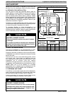
!
WARNING
ELECTRICAL SHOCK HAZARD
Failure to follow this warning could result in per‐
sonal injury or death.
Before installing, modifying or servicing system,
turn OFF the main (remote) electrical disconnect
device. There may be more than one disconnect
device.
!
CAUTION
PROPERTY DAMAGE HAZARD
Failure to follow this caution may result in proper‐
ty damage
R-410A systems operate at higher pressures than
R-22 systems. When working with R-410A sys‐
tems, use only service equipment and replace‐
ment components specifically rated or approved
for R-410A service.
LOCATION
Check local codes for regulations concerning zoning,
noise, platforms, and other issues.
Locate unit away from fresh air intakes, vents, or
bedroom windows. Noise may carry into the openings
and disturb people inside.
Locate unit in a well drained area, or support unit high
enough so that water runoff will not enter the unit.
Locate unit away from areas where heat, lint, or exhaust
fumes will be discharged onto unit (as from dryer vents).
Locate unit away from recessed or confined areas where
recirculation of discharge air may occur (refer to
CLEARANCES section of this document).
Roof-top installation is acceptable providing the roof will
support the unit and provisions are made for water
drainage and noise/vibration dampening.
NOTE: Roof mounted units exposed to wind may require
wind baffles. Consult the manufacturer for additional
information.
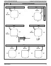
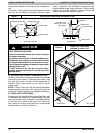
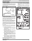
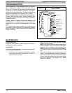
CLEARANCES
Nominal minimum clearances are 48 inches above unit
for discharge air and 18 inches on each side of the coil for
intake air. Clearance on any one side of the coil (normally
between unit and structure) may be reduced to 6 inches.
Nominal minimum clearances are based on a solid
parallel object such as a wall or roof overhang.
The clearance may be reduced for a single object with
small surface area, such as the end of a wall, outside
corner of a wall, fence section, post, etc. As a general
rule, the minimum clearance from the unit should equal
the width of the object. For example, a 6 inch fence post
should be a minimum of 6 inches from the unit.
Do not install unit under roof overhangs unless gutters are
present. A minimum vertical clearance of 48 inches is
required to the overhang.
Inside corner locations on single story structures require
evaluation. Large overhanging soffits may cause air
recirculation in a corner area even though recommended
minimum clearances are maintained. As a guide, locate
the unit far enough out so that half of the discharge grille is
out from under the soffit.
When placing two or more units side-by-side, provide a
minimum of 18 inches between units.
Provide minimum service clearance of 24 inches from
control box corner and side service panel.
Refer to Figure 1.