


INSTALLATION INSTRUCTIONS 3-phase R-410A Split System Heat Pump
506 01 5102 00 11
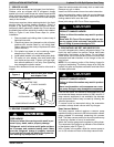
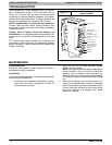
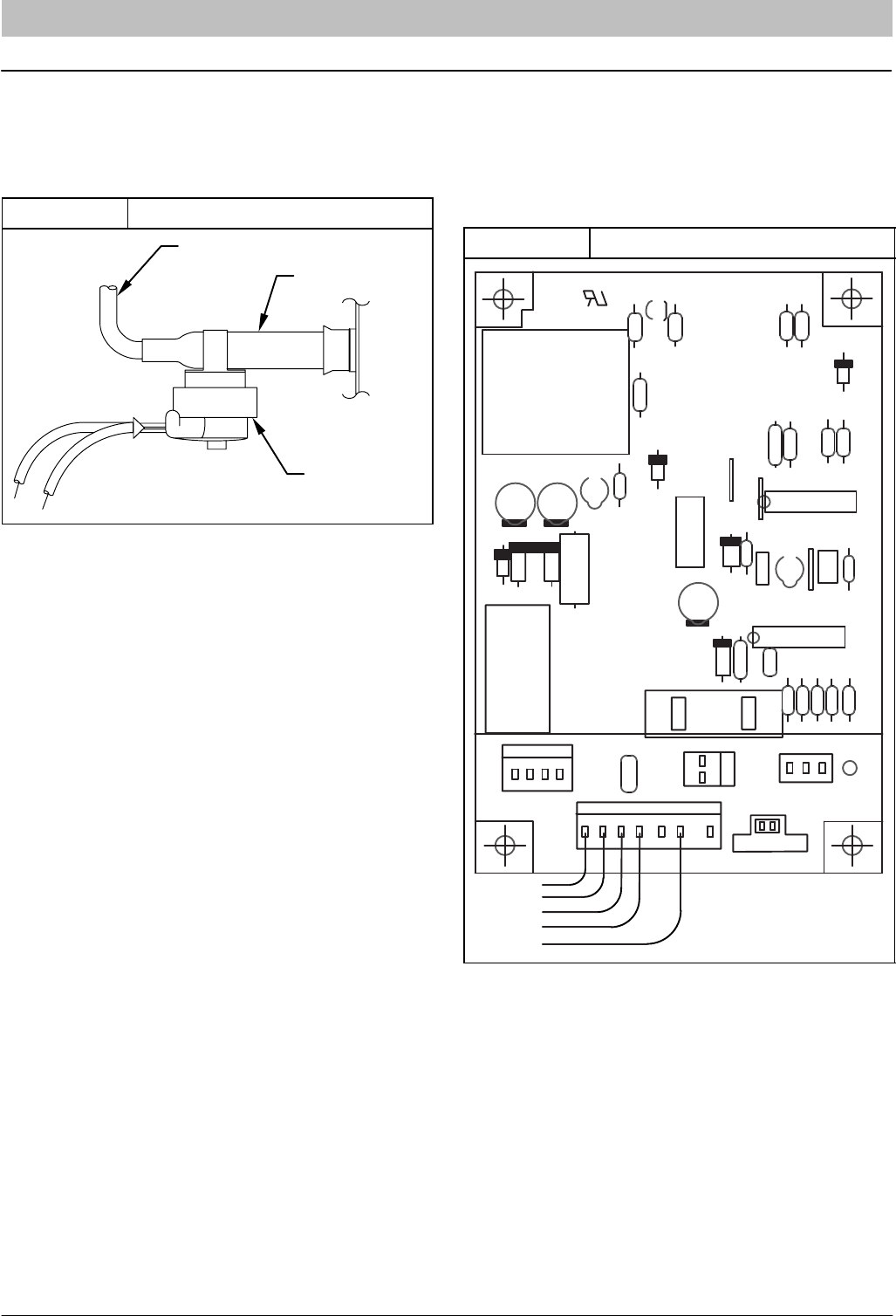
DEFROST SYSTEM
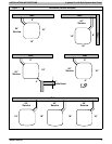
A. DEFROST THERMOSTAT
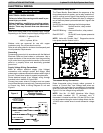
The defrost thermostat is factory installed on a short tube
stub extending from the coil end plate. Refer to Figure 12
and confirm that the thermostat is securely fastened in
place on the tube stub.
Figure 12 Defrost Thermostat
FEEDER TUBE
TUBE STUB
DEFROST
THERMOSTAT
COIL
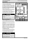
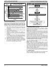
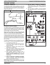
B. DEFROST CONTROL BOARD
The defrost board is a time/temperature control which
includes a field-selectable time period between defrost
cycles of 30, 60, or 90 minutes (quick-connects located
at board edge, factory set at 90 minutes).
Defrost mode is identical to cooling mode except that
outdoor-fan motor stops and second-stage heat is
turned on to continue warming conditioned space.
Initially, the defrost cycle timer starts when the contactor
is energized and a 24 VAC signal is present on the T1
terminal. Then the defrost cycle begins when the defrost
thermostat is closed and the cycle timer times out (30, 60,
90 or minutes).
To initiate a forced defrost cycle, the defrost thermostat
must be closed. This can be accomplished as follows:
1. Turn off power to outdoor unit.
2. Disconnect outdoor fan-motor lead from OF2 on
control board (refer to Figure 13). Tape lead to
prevent grounding.
3. Restart unit in heating mode, allowing frost to
accumulate on outdoor coil.
4. After a few minutes in heating mode, liquid line
temperature should drop below closing point of
defrost thermostat (approximately 32 °F).
5. Short between speed-up terminals with a
flat-bladed screwdriver (refer to Figure 13). This
reduces the timing sequence to 7, 14, or 21
seconds (30, 60, or 90 minute defrost selection,
respectively).
6. When you hear reversing valve change position,
remove screwdriver immediately; otherwise,
control will terminate normal 10-minute defrost
cycle in approximately 2 seconds.
NOTE: Length of defrost cycle is dependent upon length
of time it takes to remove screwdriver from test pins after
reversing valve has shifted.
7. Unit will remain in defrost for remainder of
defrost-cycle time or until defrost thermostat
reopens at approximately 65 °F coil temperature of
liquid line.
8. Turn off power to outdoor unit and reconnect
fan-motor lead to OF2 on control board (refer to
Figure 13).
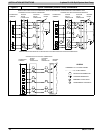
Figure 13 Defrost Control Board
R8
OF1
K1
O1
R21
C2
R6
H9C1
C US
®
R14
R13
D13
R7
C4
C10
JW2
JW1
D3
C16
C7
R28
D6
JW3
C13
R4
R1
R2
R3
R11
R5
R26
D1
D2
D10
A29
R9
D4
C19
C9
C1
OF2
CEBD430524-01A 5501A
P2
1
Y
T1 C C O
DFT
SPEEDUP
P1
1
J1
1
P3
1
J2
30 60 90
W1
R20
1
HK32EA001
C17
U1
1
U3
O
R
W
2
Y
C