


INSTALLATION INSTRUCTIONS 3-phase R-410A Split System Heat Pump
12 506 01 5102 00
START-UP PROCEDURE
1. Set indoor thermostat selector switch to OFF.
2. Turn ON all electrical disconnect devices.
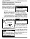
3. If unit has a crankcase heater, energize the heater
and wait 24 hours before proceeding.
4. Set indoor thermostat at desired temperature. Be
sure setpoint is below indoor ambient temperature
to call for cooling, or above indoor ambient to call
for heating.
5. Set indoor thermostat selector switch to COOL or
HEAT. Operate unit for minimum 15 minutes, then
check the system refrigerant charge.
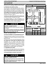
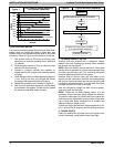
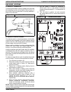
Check For Proper Phasing
Observe the LED on the Phase Monitor Relay Board. If
the LED is blinking, turn off power to the unit and swap any
two of the supply voltage wires. Turn power back on and
repeat the start-up procedure.
REFRIGERANT CHARGE
A. COOLING MODE
Outdoor units are shipped with a refrigerant charge to
match a specific indoor coil and 15 feet of refrigerant line.
If shorter or longer refrigerant lines or a different indoor
coil are used, the charge will have to be adjusted.
For different line lengths, add or remove charge based on
0.6 ounces charge per foot of difference. For example, a
25 foot line set is 10 feet longer than the specified 15 feet.
Add 0.6 ounces charge for each of the extra 10 feet:
10 x 0.6 = 6.0 ounces additional charge
This outdoor unit is designed for use only with indoor coils
that utilize a TXV refrigerant metering device. With an
indoor TXV, use the subcooling method to make final
charge adjustments:
NOTE: Only use subcooling charging method when
S outdoor ambient temperature is between 70_F and 100_F
S indoor temperature is between 70_ and 80_F
S line set is less that 80 feet.
1. Operate unit a minimum of 15 minutes before
checking charge.
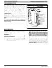
NOTE: If outdoor unit has a 2-speed fan motor,
motor will operate in low speed when outdoor
ambient temperature is below 82 °F. Pull one of the
yellow low voltage wires off the fan control and the
unit will default to high speed fan for servicing.
Reconnect wire after servicing.
2. Measure liquid service valve pressure by attaching
an accurate gauge to service port.
3. Measure liquid line temperature by attaching an
accurate thermistor type sensor or electronic
thermometer to liquid line near outdoor coil.
4. Refer to unit rating plate for required subcooling
temperature.
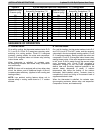
5. Refer to Figure 14. Find the required liquid line
temperature where the rating plate subcooling
temperature intersects measured liquid service
valve pressure.
6. If the measured liquid line temperature is higher
than the chart number, add refrigerant to lower the
measured temperature.
NOTE: When adding refrigerant, charge in liquid
form, using a flow restricting device, into the
suction port.
If the measured liquid line temperature is lower
than the chart number, reclaim refrigerant to raise
the measured temperature.
Tolerance is | 3 °F.
B. HEATING MODE
To check system operation during heating cycle, refer to
the Tech Label on outdoor unit. This chart indicates
whether a correct relationship exists between system
operating pressure and air temperature entering indoor
and outdoor units. If pressure and temperature do not
match on chart, system refrigerant charge may not be
correct. Do not use chart to adjust refrigerant charge.
NOTE: When charging is necessary during heating
season, charge must be weighed in accordance with unit
rating plate ±0.6 ounces per foot of a inch liquid line
above or below 15 feet respectively.