


INSTALLATION INSTRUCTIONS 3-phase R-410A Split System Heat Pump
8 506 01 5102 00
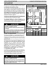
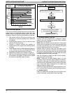
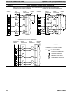
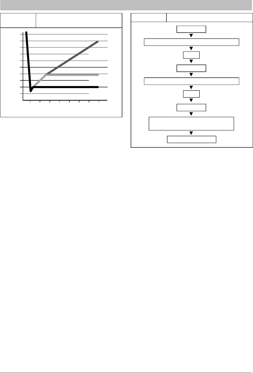
Figure 7
Deep Vacuum Gauge Response
and System Conditions
500
MINUTES
01
246
1000
1500
LEAK IN
SYSTEM
VACUUM TIGHT
TOO WET
TIGHT
DRY SYSTEM
2000
MICRONS
2500
3000
3500
4000
4500
5000
375
Triple Evacuation Method
The triple evacuation method should only be used when
system does not contain any water in liquid form and
vacuum pump is only capable of pulling down to 28 inches
of mercury. Refer to Figure 8 and proceed is as follows:
1. Pull system down to 28 inches of mercury and
allow pump to continue operating for an additional
15 minutes.
2. Close manifold valves or valve at vacuum pump
and shut off vacuum pump.
3. Connect a nitrogen cylinder and regulator to
system and fill with nitrogen until system pressure
is 2 psig.
4. Close nitrogen valve and allow system to stand for
1 hour. During this time, dry nitrogen will diffuse
throughout the system absorbing moisture.
5. Repeat this procedure as indicated in Figure 8.
6. After the final evacuate sequence, confirm there
are no leaks in the system. If a leak is found, repeat
the entire process after repair is made.
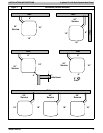
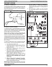
Figure 8 Triple Evacuation Sequence
CHECK FOR TIGHT, DRY SYSTEM
(IF IT HOLDS DEEP VACUUM)
EVACUATE
BREAK VACUUM WITH DRY NITROGEN
WAIT
EVACUATE
CHARGE SYSTEM
BREAK VACUUM WITH DRY NITROGEN
EVACUATE
WAIT
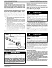
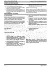
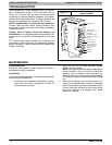
I. OPENING SERVICE VALVES
Outdoor units are shipped with a refrigerant charge
sealed in the unit. Opening the service valves releases
this charge into the system.
NOTE: Open the Suction service valve first. If the Liquid
service valve is opened first, oil from the compressor may
be drawn into the indoor coil TXV, restricting refrigerant
flow and affecting operation of the system.
Remove Suction service valve cap and insert a hex
wrench into the valve stem. Hold the valve body steady
with an end-wrench and back out the stem by turning the
hex wrench counterclockwise. Turn the stem until it just
contacts the rolled lip of the valve body.
After the refrigerant charge has bled into the system,
open the Liquid service valve.
NOTE: These are not back-seating valves. It is not
necessary to force the stem tightly against the rolled lip.
The service valve cap is a primary seal for the valve and
must be properly tightened to prevent leaks. Make sure
cap is clean and apply refrigerant oil to threads and
sealing surface on inside of cap.
Tighten cap finger tight and then tighten additional 6 of a
turn (1 wrench flat) to properly seat the sealing surfaces.
J. GAUGE PORTS
Check for leaks at the schrader ports and tighten valve
cores if necessary. Install plastic caps finger tight.