


INSTALLATION INSTRUCTIONS 3-phase R-410A Split System Heat Pump
506 01 5102 00 13
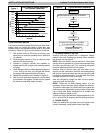
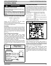
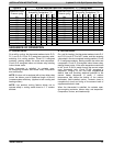
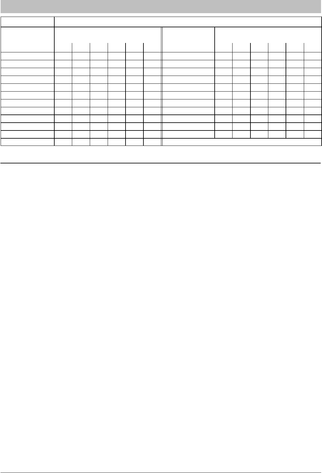
Figure 14 R-410A Required Liquid Line Temperature (°F) - Cooling Mode
Measured Liquid
Pressure (psig)
Rating Plate (required)
Subcooling Temperature (°F)
Measured Liquid
Pressure (psig)
Rating Plate (required)
Subcooling Temperature (°F)
6 8 10 12 14 16 6 8 10 12 14 16
251 78 76 74 72 70 68 364 104 102 100 98 96 94
259 80 78 76 74 72 70 374 106 104 102 100 98 96
266 82 80 78 76 74 72 384 108 106 104 102 100 98
274 84 82 80 78 76 74 395 110 108 106 104 102 100
283 86 84 82 80 78 76 406 112 110 108 106 104 102
291 88 86 84 82 80 78 416 114 112 110 108 106 104
299 90 88 86 84 82 80 427 116 114 112 110 108 106
308 92 90 88 86 84 82 439 118 116 114 112 110 108
317 94 92 90 88 86 84 450 120 118 116 114 112 110
326 96 94 92 90 88 86 462 122 120 118 116 114 112
335 98 96 94 92 90 88 474 124 122 120 118 116 114
345 100 98 96 94 92 90
SEQUENCE OF OPERATION
A. COOLING MODE
On a call for cooling, the thermostat makes circuits R-O,
R-Y, and R-G. Circuit R-O energizes reversing valve,
switching it to cooling position. Circuit R-Y energizes
contactor, starting outdoor fan motor and compressor.
Circuit R-G energizes indoor unit blower relay, starting
indoor blower motor.
When thermostat is satisfied, its contacts open,
de-energizing contactor and blower relay. Compressor
and motors stop.
NOTE: If indoor unit is equipped with a time-delay relay
circuit, the blower runs an additional length of time to
increase system efficiency. (Applies to both cooling and
heating modes.)
NOTE: Low ambient cooling feature allows unit to
operate safely in cooling mode down to 0_ F outdoor
ambient.
B. HEATING MODE
On a call for heating, the thermostat makes circuits R-Y
and R-G (circuit R-O is NOT made, and the reversing
valve stays in the de-energized, heating position). Circuit
R-Y energizes contactor, starting outdoor fan motor and
compressor. Circuit R-G energizes indoor blower relay,
starting blower motor. If the room temperature continues
to fall, circuit R-W2 is made through the second-stage
room thermostat bulb. Circuit R-W2 energizes a
sequencer, bringing on the first bank supplemental
electric heat and providing electrical potential to the
second heater sequencer (if used). If outdoor
temperature falls below the setting of the outdoor
thermostat (field-installed option), contacts close to
complete the circuit and bring on the second bank of
supplemental electric heat.
When the thermostat is satisfied, its contacts open,
de-energizing contactor, blower relay, and sequencer.
Compressor, motors, and heaters stop.