


UB USER INSTRUCTIONS ENGLISH 71569247 07-04
Page 25 of 32
®
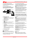
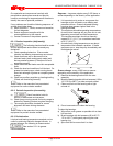
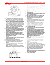
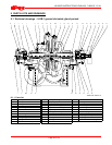
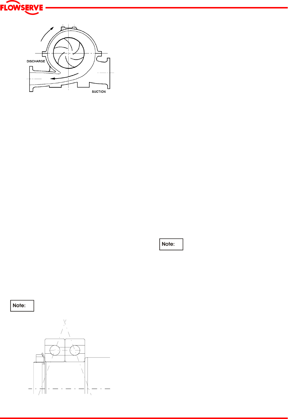
The rotor always rotates towards the expanding
section of the volute
c) The diaphragm plate complete with its bush must
be fitted on to the shaft between the two impellers.
d) Fit the two shaft sleeves, O-rings (when fitted)
and shaft nuts and lightly secure the impellers on
the shaft. Take care to protect the sleeve O-rings
(when fitted) from damage on the shaft threads.
The sleeves and nuts define the impeller position
on the pump shaft and hence in the pump casing.
Initially position the impellers centrally on its
keyway. This position may be adjusted slightly
later on in the assembly process.
e) It is recommended that gasket sealing compound
Loctite 574 or equivalent is used between sleeve
and impeller mating faces to protect the shaft
from the liquid pumped.
f) When mechanical seals are fitted the rotating
parts can be slid onto the sleeves before the
sleeves are fitted onto the shaft. The seal locking
collars should be left loose.
Refer to any special instructions supplied
with the mechanical seal.
g) If gland packing is used fit the glands.
h) Fit seal covers complete with seal seat, water
throwers and bearing covers complete with
gaskets.
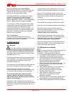
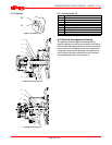
i) Fit the bearings onto the shaft. The main thrust
bearing is at the non-drive end.
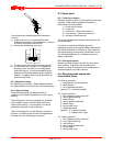
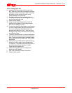
Where double row bearings are fitted
these must be assembled 'back to back' as below:
The bearings must be heated up to 100 ºC (212 ºF)
using a hot plate, oil bath or induction heater and
slid onto the shaft. Ensure bearing is fully seated
against the bearing distance piece and the distance
piece is located up to the shaft shoulder.
j) Fill both sides of bearing with grease.
k) Fit the bearing lockwasher and tighten the
bearing shaft nut.
l) Peen a segment of the copper lockwasher over a
flat on the bearing locknut.
m) Slip casing rings, loosely over the impeller hubs.
n) Slide the bearing housings over the bearings.
Ensure bearings are located square in the
bracket bore.
o) One third fill the space between bearing cover
and bearing with grease. Secure bearing cover,
complete with gasket.
p) Fit the coupling distance piece and pump half
coupling. Fit copper lockwasher and secure
coupling nut. Peen a segment of the copper
lockwasher over a flat on the coupling nut.
6.10.4 Casing lower half
a) If required, drive in two new locating dowels on
the horizontal flange.
b) Coat the faces of the bearing housing brackets
with liquid sealant to protect against corrosion.
c) Place the complete rotating assembly into the
casing ensuring that impeller rings and diaphragm
plate are in the correct position to allow the anti-
rotation tongues to locate correctly in the anti-
rotation grooves in the casing bores.
The anti-rotation grooves in the bottom
half casing are bigger in diameter than those in
the top.
d) Locate the bearing housings in the machined
spigots in the casing and torque up the fixing
screws.
e) Check rotor for free rotation.
f) Centralize the impellers within the casing
waterway by adjusting the shaft nut, if necessary.
Using a C-spanner fully tighten the shaft nuts and
lock with the two radial socket head screws.
g) Set the seals, if fitted, to the correct working
length and tighten the seal collar screws.
Refer to any special instructions supplied
with the mechanical seal.
h) Check for free rotation.