


UB USER INSTRUCTIONS ENGLISH 71569247 07-04
Page 11 of 32
®
3 PUMP DESCRIPTION
3.1 Configurations
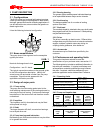
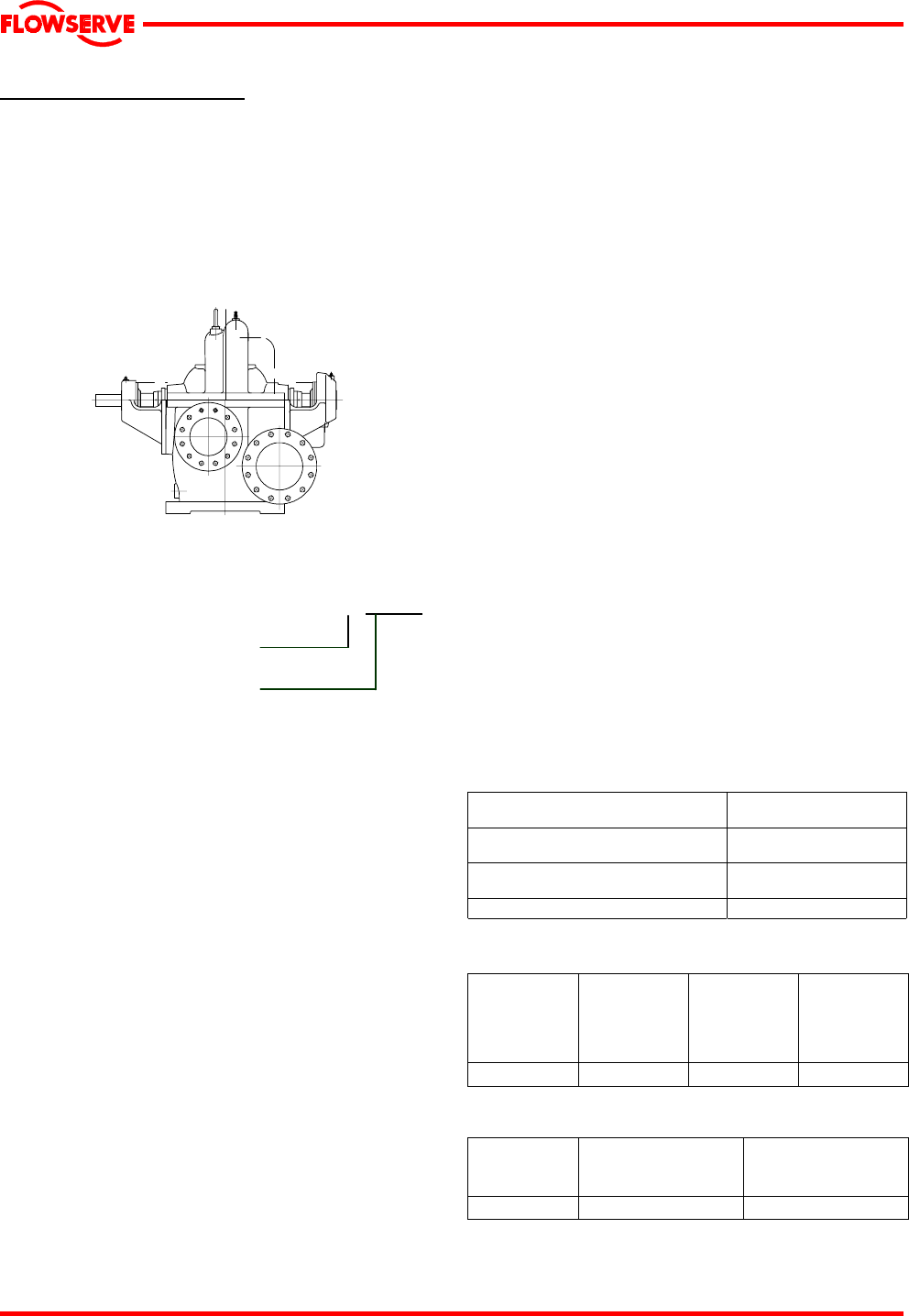
The 8-UB-1pump is a horizontal split casing two stage
volute type centrifugal pump designed for water works,
drainage, general service and circulating applications. It
can be used with motor, steam turbine and gasoline or
diesel engine drive.
It has the following horizontal configuration:
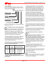
3.2 Name nomenclature
The pump size will be engraved on the nameplate
typically as below:
8-UB- 1
Nominal discharge branch size
Configuration – see 3.1 above
The typical nomenclature above is the general guide
to the UB configuration description. Identify the
actual pump size and serial number from the pump
nameplate. Check that this agrees with the
applicable certification provided.
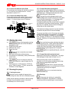
3.3 Design of major parts
3.3.1 Pump casing
The pump has its main casing gasket axial to the
shaft allowing maintenance to the rotating element by
removing the top half casing. Suction and discharge
branches are in the bottom half and therefore remain
undisturbed.
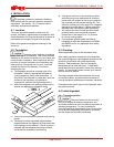
3.3.2 Impellers
The impellers are fully shrouded and may be fitted
with optional hub rings.
3.3.3 Shaft
The large diameter stiff shaft, mounted on bearings,
has a keyed drive end.
3.3.4 Pump bearings and lubrication
Ball bearings are fitted as standard and may be either
oil or grease lubricated.
3.3.5 Bearing housing
Two grease nipples enable grease lubricated bearings
to be replenished between major service intervals.
3.3.6 Seal housing
The design enables one of a number of sealing
options to be fitted.
3.3.7 Shaft seal
The mechanical seal(s), attached to the pump shaft, seals
the pumped liquid from the environment. Gland packing
may be fitted as an option.
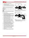
3.3.8 Driver
The driver is normally an electric motor. Different drive
configurations may be fitted such as internal combustion
engines, turbines, hydraulic motors etc driving via
couplings, belts, gearboxes, drive shafts etc.
3.3.9 Accessories
Accessories may be fitted when specified by the
customer.
3.4 Performance and operating limits
This product has been selected to meet the
specifications of your purchase order, see section 1.5.
The following data is included as additional information to
help with your installation. It is typical, and factors such
as temperature, materials, and seal type may influence
this data. If required, a definitive statement for your
particular application can be obtained from Flowserve.
3.4.1 Operating limits
Pumped liquid temperature limits*
- 20 to + 120 ºC
(- 4 to + 250 ºF)
Maximum ambient temperature*
- 20 to + 40 ºC
(- 4 to +104 ºF)
Maximum soft solids in suspension*
up to 3 % by volume
(refer for size limits)
Maximum pump speed
refer to the nameplate
*Subject to written agreement from Flowserve.
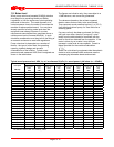
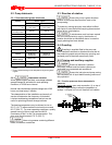
3.4.2 Pump and impeller data
Pump
size
Impeller
minimum
passage
size
mm (in.)
Nominal
wear
ring
diameter
mm (in.)
Mean
radial
wear ring
clearance
mm (in.) *
8-UB-1 17.5 (0.69) 266.7 (10.5) 0.19 (0.0075)
*May be up to 0.13 mm (0.005 in.) larger if casing ring and impeller
have a tendency to gaul.
Pump
size
Nominal diaphragm
bush diameter
mm (in.)
Mean radial
bush clearance
mm (in.)
8-UB-1 127 (5) 0.11 (0.0045)