


UB USER INSTRUCTIONS ENGLISH 71569247 07-04
Page 23 of 32
®
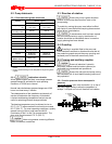
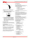
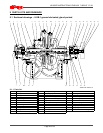
1 – impeller
1 – diaphragm bush
(optional: 2 - mechanical seals
2 - impeller wear rings)
6.5 Tools required
A typical range of tools that will be required to
maintain these pumps is listed below.
Readily available in standard tool kits, and dependent
on pump size:
• Open ended spanners (wrenches) to suit up to
M 24 (
7
/
8
in.) screws/nuts
• Socket spanners (wrenches), up to M 24 (
7
/
8
in.)
screws
• Allen keys, up to 6 mm (¼ in.) A/F
• Range of screwdrivers
• Soft mallet
More specialized equipment:
• Bearing pullers
• Bearing induction heater
• Dial test indicator
• C-spanner (wrench) - for removing shaft nut.
(If difficulties in sourcing are encountered, consult
Flowserve.)
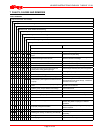
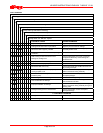
6.6 Fastener torques
Torque Nm (lbf·ft)
Bolt size
Pump feet
fasteners
All other
fasteners
M8 (
5
/
16
in.)
M10 (⅜ in.)
M12 (½ in.)
M16 (⅝ in.)
M20 (¾ in.)
M24 (⅞ in.)
-
-
63 (46)
170 (125)
340 (250)
590 (435)
10 (7)
20 (15)
34 (25)
84 (62)
165 (120)
285 (210)
6.7 Renewal clearances
As wear takes place between the impeller, casing ring
and diaphragm bush the overall efficiency of the pump
set will decrease. To maintain optimum efficiency it is
recommended that rings and bush are replaced and the
impeller renovated when the radial clearance detailed in
section 3.4.2 has doubled.
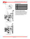
6.8 Disassembly
Refer to section 1.6, Safety, before dismantling
the pump.
Before dismantling the pump for
overhaul, ensure genuine Flowserve replacement
parts are available.
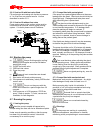
To dismantle the pump consult the sectional
drawings. See section 8, Parts lists and drawings.
a) Isolate motor and lock off electrical supply in
accordance with local regulations.
b) Isolate suction and discharge valves.
c) Remove coupling guards and disconnect the
coupling halves.
d) Drain pump casing. Remove any auxiliary piping
if applicable.
e) Release the copper lockwasher securing the
coupling nut and remove the pump half coupling.
f) Unbolt the glands/seal covers from the casing.
If glands are split type, remove completely.
g) With a suitable punch, drive out the two locating
dowels which are used on the horizontal split
flange to align the upper and lower half casings.
h) Remove the bolts, which hold the upper and lower
half of the casing together, and remove the upper
half. Tapped holes are provided in the joint flange
to enable the use of forcing bolts to loosen the joint.
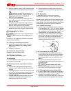
i) Lift the casing upper half using the two eye bolts
provided.
Do NOT use this method to lift the bottom
half or complete pump casing.
j) Remove the 6 – screws securing each bearing
bracket to the bottom half casing.
k) Lift out rotor assembly. Use care in slinging,
handling and supporting of the rotor for
subsequent dismantling. Place rotor securely on
two support blocks.
l) When removing the rotor assembly, the casing rings
and diaphragm plate will be loosely attached to the
rotor.
m) Remove bearing covers and slide bearing housings
off bearings.
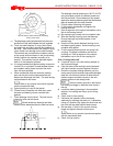
n) Release the copper lockwasher securing the
bearing locknut at the non-drive end and remove the
locknut. Pull off both ball bearings using a suitable
puller; ensuring force is applied to inner race only.
Retain the bearing distance pieces and coupling
distance piece for future use. Remove the bearing
covers.
o) Depending on configuration remove glands/seal
covers, packing and lantern ring/mechanical seal.
Refer to any special instructions supplied
with the mechanical seal.
p) Remove the two socket head screws securing
each shaft sleeve nut. Using C-spanner remove
shaft nuts. Slide off shaft sleeves.