


UB USER INSTRUCTIONS ENGLISH 71569247 07-04
Page 15 of 32
®
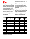
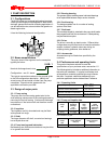
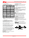
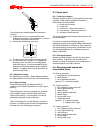
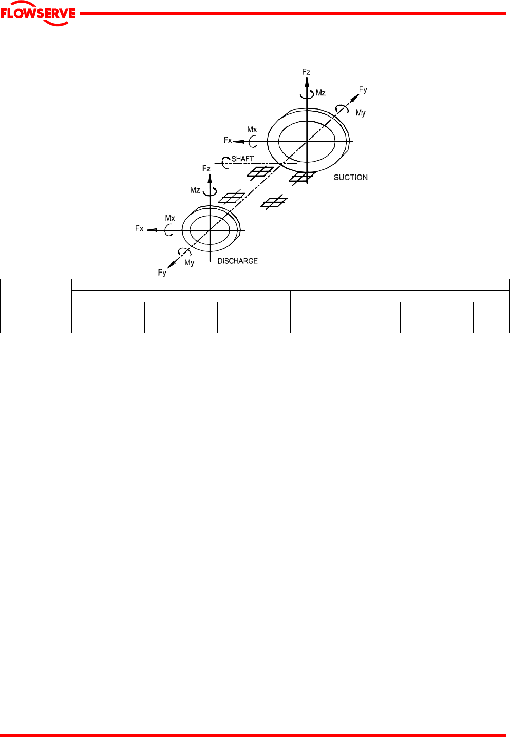
4.5.3 Maximum forces and moments allowed on the pump suction and discharge flanges of horizontal
shaft pumps
Maximum forces (F) in kN (lbf) and maximum moments (M) in kNm (lbf·ft)
Suction Discharge
Type and size
Fx Fy Fz Mx My Mz Fx Fy Fz Mx My Mz
8-UB-1
7.35
(1653)
5.78
(1299)
4.20
(944)
4.25
(3134)
2.25
(1659)
3.00
(2212)
3.84
(863)
4.40
(989)
3.20
(719)
2.20
(1622)
1.20
(885)
1.60
(1180)
Notes:
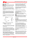
1) F = External force (tension or compression).
M = External moment, clockwise or counter-clockwise.
2) Forces and moments may be applied simultaneously in any
direction.
3) Values apply to all materials.
4) Higher loads may be applicable, if direction and magnitude of
individual loads are known, but these need written approval
from Flowserve Pumps.
5) Pumps must be on rigid foundations and baseplates must be
fully grouted
6) Pump/baseplate should not be used as pipe anchor. Suction
and discharge piping should be anchored as close as possible
to the pump flanges to reduce vibration and prevent strain on
the pump casing. Expansion joints are recommended. They
must be properly tied and located on the side of the pipe anchor
away from the pump.
7) The pump mounting bolt torques specified must be used to
prevent relative movement between the pump casing and
baseplate. (See section 6.6, Fastener torques.) The bolt
material must have a minimum yield strength of 600 N/mm
2
(87 000 lb/in.
2
).
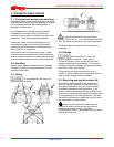
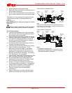
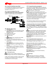
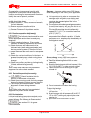
4.5.4 Discharge piping
See section 4.5.2 for typical pipework design.
A non-return valve should be located in the discharge
pipework to protect the pump from excessive back
pressure and hence reverse rotation when the unit is
stopped.
Pipework reducers should have a maximum total
angle of divergence of 9 degrees.
Fitting an isolation valve will allow easier maintenance.
4.5.5 Auxiliary piping
4.5.5.1 Drains
Pipe pump casing drains and gland leakage to a
convenient disposal point.
4.5.5.2 Pumps fitted with packed gland
When suction pressure is below ambient pressure it
is necessary to feed the gland packing with liquid to
provide lubrication and prevent the ingress of air.
This is normally achieved with a supply from the
pump discharge volute to the stuffing box.
If the pumped liquid is dirty and cannot be used for
sealing, a separate clean compatible liquid supply to
the gland at 1 bar (15 psi) above suction pressure is
recommended.
4.5.5.3 Pumps fitted with mechanical seals
Single seals requiring re-circulation will normally be
provided with the auxiliary piping from pump casing
already fitted.
If the seal requires an auxiliary quench then a
connection must be made to a suitable source of
liquid flow, low pressure steam or static pressure from
a header tank. Recommended pressure is 0.35 bar
(5 psi) or less. Check General arrangement drawing.