


UB USER INSTRUCTIONS ENGLISH 71569247 07-04
Page 14 of 32
®
• Prevent excessive external pipe load
• Never draw piping into place by applying force to
pump flange connections
• Do not mount expansion joints so that their force,
due to internal pressure, acts on the pump flange
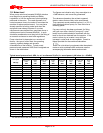
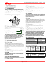
The table in 4.5.3 summarizes the maximum forces
and moments allowed on horizontal shaft pump
casings.
Ensure piping and fittings are flushed
before use.
Ensure piping for hazardous liquids is arranged
to allow pump flushing before removal of the pump.
4.5.2 Suction piping
a) The inlet pipe should be one or two sizes larger
than the pump inlet bore and pipe bends should
be as large a radius as possible.
b) Pipework reducers should be conical and have a
maximum total angle of divergence of 15 degrees.
c) On suction lift the piping should be inclined up
towards the pump inlet with eccentric reducers
incorporated to prevent air locks.
d) On positive suction, the inlet piping must have a
constant fall towards the pump.
e) Flow should enter the pump suction with uniform
flow, to minimize noise and wear. This is
particularly important on large or high-speed
pumps, which should have a minimum of five
diameters of straight pipe on the pump suction
between the elbow and inlet flange. See section
10.3, Reference 1, for more detail.
f) Inlet strainers, when used, should have a net `free
area' of at least three times the inlet pipe area.
g) Do not install elbows at an angle other than
perpendicular to the shaft axis. Elbows parallel
to the shaft axis will cause uneven flow.
h) Except in unusual circumstances strainers are
not recommended in inlet piping. If considerable
foreign matter is expected a screen installed at
the entrance to the wet well is preferable.
i) Fitting an isolation valve will allow easier
maintenance.
j) Never throttle pump on suction side and never
place a valve directly on the pump inlet nozzle.
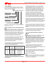
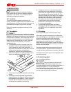
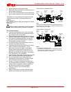
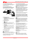
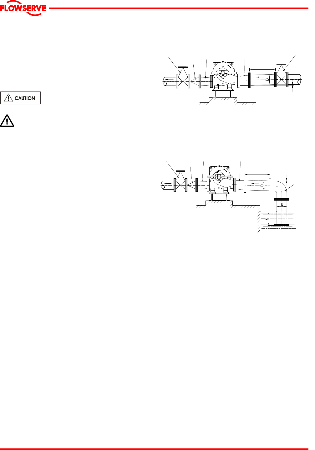
Typical design – flooded suction
Note:
Ideally reducers should be limited to one pipe diameter change,
ie 150 mm (6 in.) to 200 mm (8 in.). Must have a maximum total
angle of divergence of 15 degrees.
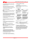
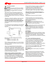
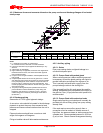
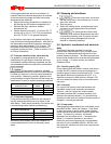
Typical design – suction lift
Notes:
1. S = Minimum submergence >3E.
2. Ideally reducers to be limited to one pipe diameter change,
ie 150 mm (6 in.) to 200 mm (8 in.). Must have a maximum
total angle of
divergence of 15 degrees.
Non
return
valve
Concentric
conical
reducer
Eccentric
conical
reducer
>
5D
Discharge
isolating
valve
Suction
isolating
valve
Slope up from
pump suction
Discharge
isolating
valve
Non
return
valve
Concentric
conical
reducer
Eccentric
conical
reducer
>
5D
Long
radius
bend
Slope down
from pump
suction