


5
WARNING
Biohazard can
cause serious
personal injury.
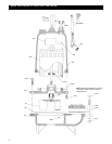
5. Remove and discard the mechanical seal and stationary
seat assembly. DO NOT damage the motor shaft or the
stationary seat bore.
6. Inspect and wipe clean the stationary seat bore.
7. To install the new stationary seat into the seal housing,
lubricate the stationary seat bore and motor shaft with
clean motor insulating oil. Using Goulds mechanical seal
installation tool (A02A013), slide the stationary seat
fully and squarely into the seal housing.
8. With a clean, lint free cloth, wipe the stationary face
clean of all lubricating oil or debris. DO NOT scratch or
otherwise damage the seal face.
9. Lubricate the inside of the rotary elastomer with clean
motor insulating oil. Using the Goulds installation tool,
slide the seal rotary assembly onto the motor shaft and
seat fully against the stationary seat. Remove the seal
installation tool.
10. Install the impeller onto the motor shaft by turning the
impeller on CLOCKWISE, tighten securely. Treat the
impeller with Loctite™ #271 and securely install. When
provided, securely install the impeller locknut.
11. Fill the motor cover with motor special insulating oil to
within
1
⁄2" (13 mm) of the seal chamber housing. Tape
drain plug with Teflon™ tape and install plug securely.
12. Reassemble casing and new casing gasket to pump
assembly by installing the four casing hex cap screws,
torquing in sequence to 35 lbs ft (47 Ν m).
NOTICE:FOLLOW THE INSTRUCTIONS PROVIDED
IN THE “WIRING AND GROUNDING” AND
“OPERATION” SECTIONS OF THE
MANUAL AFTER UNIT DISASSEMBLY,
REASSEMBLY.
POWER CABLE REPLACEMENT
1. To gain access to the motor cover screws follow steps 1
through 6 in the “MECHANICAL SEAL
REPLACEMENT” section of this manual.
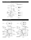
2. Remove the power cable strain relief (484B) assembly
from the motor cover and slide up the cable.
3. Remove the four bearing housing socket head screws
(371C). Carefully slide the motor cover from the motor
assembly. DO NOT damage the power cable.
4. Disconnect the power cable wires from the motor
assembly (338).
5. Remove cable from motor cover, inspect and replace as
required, following the procedures provided.
NOTICE: DISCARD STRAIN RELIEF ASSEMBLY.
THEY CAN NOT BE REUSED.
6. Install new motor cable strain relief assembly onto cable,
sliding the hex gland on first, then the washer and finally
the packing. Insert the cables into the motor cover hole.
Pull an appropriate amount of cable through the motor
cover to allow for connecting the cable leads. DO NOT
tighten the strain relief gland.
WARNING
Hazardous
voltage
Disassembly/Assembly
FAILURE TO DISCONNECT AND
LOCKOUT ELECTRICAL POWER
BEFORE ATTEMPTING ANY
MAINTENANCE CAN CAUSE
SHOCK, BURNS OR DEATH.
NOTICE: FOLLOW ALL SAFETY AND LIFTING
INSTRUCTIONS PROVIDED IN THIS
MANUAL.
• Following the slide rail instructions, remove the pumping
unit from the sewage containment area.
UNIT MUST BE FLUSHED AND
DISINFECTED, INSIDE AND OUT,
PRIOR TO SERVICING.
MECHANICAL SEAL REPLACEMENT
1. Follow ALL instructions provided in the
“DISASSEMBLY” section of this manual.
2. To gain access to the pump impeller and mechanical seal
remove the four casing hex cap screws (372D). Remove
casing (100) and casing gasket (351); discard the gasket.
FAILURE TO REMOVE DRAIN
PLUG CAREFULLY CAN CAUSE
HOT OIL TO ERUPT FROM OIL
RESERVOIR CAUSING PERSONAL
INJURY OR PROPERTY DAMAGE
3. Removal of the mechanical seal assembly (387) requires
draining the special insulating oil from the motor cover.
This is accomplished by removing the drain plug and
draining the oil into an adequately sized clean receptacle.
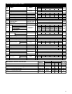
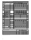
See “ENGINEERING DATA” section for required
volume.
4. To remove the impeller (101), it may be necessary to
heat the impeller and impeller locknut (304), three phase
motors only, with a torch. Use no more heat that is
necessary, as excess heat will damage the mechanical
seal. Secure the impeller from rotation, and remove
the impeller lock nut, by turning the lock nut
COUNTERCLOCKWISE. Remove the impeller
from the motor shaft by holding the motor shaft with a
screw driver and turning the impeller COUNTER-
CLOCKWISE.
Hazardous pressure can
cause personal injury or
property damage.
CAUTION