


3
NOTICE:DURING PUMP OPERATION, INSURE THAT
THE LIQUID LEVEL DOES NOT DROP
BELOW THE PUMP MOTOR FOR
EXTENDED PERIODS. THIS CAN CAUSE
THE PUMP MOTOR TO OVERHEAT,
CAUSING MOTOR DAMAGE AND
VOIDING THE WARRANTY.
Pump Motor Control Panels
• Control panels shall be in accordance with local and
National Electrical Code requirements.
• Single phase installations shall be equipped with a Goulds’
“SES” or “A” Series panel, or AS A MINIMUM, a
control panel with a properly sized magnetic contactor and
a disconnect switch.
• Three phase installations shall be equipped with a Goulds’
“SES” or “A” Series panel, or AS A MINIMUM with a 3
pole circuit breaker, an across the line magnetic starter
NEMA rated for the appropriate horsepower, ambient
compensated Quick Trip Class 10 overload relays.
Wiring and Grounding
• Use only stranded copper wire to motor and ground. The
ground wire must be at least as large as the wires to the
motor. Wires should be color coded for ease of
maintenance.
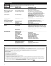
Install, ground and wire
according to local and National
Electrical Code requirements.
Install an all leg disconnect
switch near the pump.
Disconnect and lockout electrical
power before installing or
servicing pump.
Electrical supply MUST match pump’s nameplate
specifications. Incorrect voltage can cause fire,
damage motor and voids warranty.
Single phase motors are equipped with automatic
thermal protectors which open the motor’s
electrical circuit when an overload exists. This
can cause the pump to start unexpectedly and
without warning.
Some models are equipped with a 3-prong
grounded plug and MUST be used in a grounded
3-wire receptacle. DO NOT modify the plug or
remove the ground prong.
• Where cables must be spliced or connected to the motor
leads, splices MUST be water tight. Commercially
available potting or heat shrink kits may be used, if
allowed by local or federal regulations.
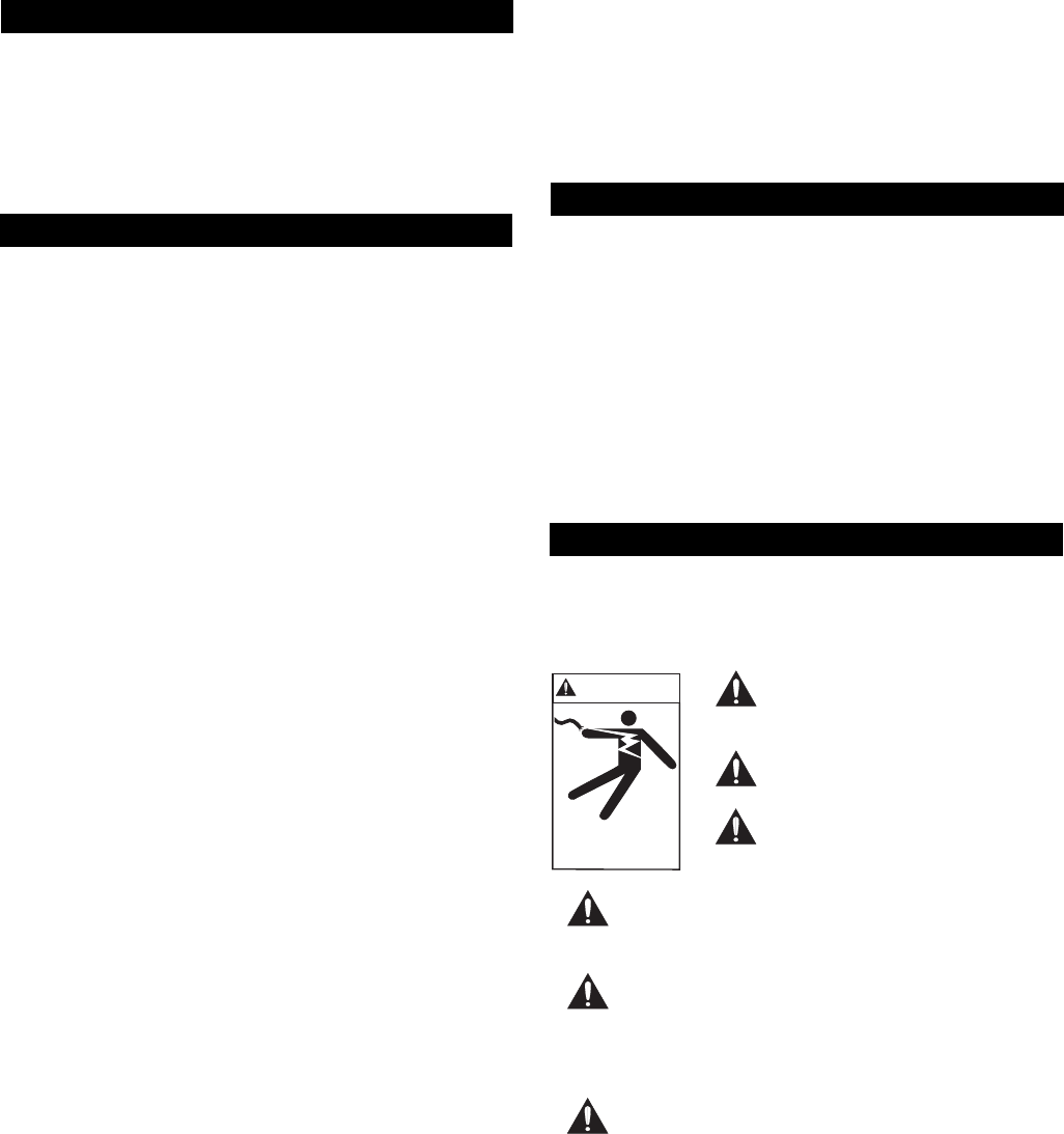
WARNING
Hazardous voltage
can shock, burn or
cause death.
Access Doors
• Access doors can be single or double leaf design. Doors
should include a lifting handle and a lock provision for
tamper resistant operation. Standard and heavy duty steel
or aluminum doors are available.
• The pit access door must be of sufficient size to allow for
inspection, maintenance and crane or hoist service.
Liquid Level Controls
• Single float operation can be used on
1
⁄3 and
1
⁄2 HP models.
Mounting of the float switch must be checked by the
installer to insure proper turn on and turn off. The pump
may be plugged directly into the piggy back style plug
located on the cord of the float switch.
• The recommended float operation sequence used with a
control panel requires a three or four float system. In the
three float system, the floats are designated SW-1 for the
bottom float, SW-2 for the middle float and SW-3 for the
top float. In a four float system the fourth float is
designated SW-4.
• Simplex Control – The rising liquid level raises float
SW-2, turning on the pump. When the liquid level falls
sufficiently, SW-1 will turn the pump off. If the influent
is excessive, or if the pump fails to operate correctly,
SW-3 will activate an alarm, which will remain on until
manually reset.
• Duplex Control – The duplex control will alternate the
two pumps, causing the lead pump to change at each
system cycle. When equipped with three floats, the
system will cycle the same as the simplex control,
described above, except that the SW-1 will cause the
lead pump to alternate.
• If the influent is excessive, or if the lead pump fails to
operate correctly, the rising level will activate SW-3,
turning on the lag pump and the alarm. As before the
alarm must be manually reset.
• Four Float Control – The four float system operates the
same as the duplex control system, except that float
SW-3 will not turn on the alarm. In this system SW-4
turns on the alarm, which again must be manually reset.
• Several different float controls are available from the
Goulds Catalog.
NOTICE:POSITION THE FLOATS SO THAT THEY
DO NOT SNAG OR TANGLE ON THE PUMP,
DISCHARGE PIPING, OR OTHER
EQUIPMENT.
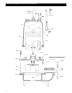
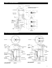
• The lower most float turns the unit off and should be set as
shown in the “TYPICAL PLUMBING and
INSTALLATION” drawing provided in this manual.
• Increasing the distance between the SW-1 and SW-2 floats
lengthens the running time. One (1) minute is the
minimum recommended pump cycle time.