


33606 Rev D 16 01-03
BUILDER'S CHOICE SERIES INSTALLATION INSTRUCTIONS
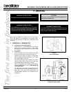
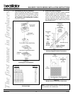
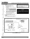
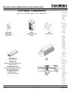
Figure 27
Standing Pilot Ignition Wiring Diagram
14-3 with Ground Romex is the recommended
wiring to the appliance Junction Box.
Detailed picture of the Junc-
tion Box (Optional for Stand-
ing Pilot Appliances).
4. WIRING
Standing Pilot Ignition - Millivolt System
a. Appliance Requirements
A wiring diagram is shown in Figure 27.
b. Wall Switch
The installer shall supply UL or in Canada, CSA-
listed wall switch and wiring between appliance
and wall switch. This appliance was tested with
eighteen feet of UL Listed 18 ga. Type CL2 105°C,
two conductor thermostat wire. If other wiring
materials are used they shall comply with local
codes or in the absence of local codes, with
National Electrical Code ANSI/NFPA 70-latest
edition or Canadian Electrical Code CSA C22.1.
c. Optional Accessories Requirements
Wiring for optional accessories should be done
now to avoid reconstruction.
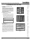
5. JUNCTION BOX INSTALLATION AND
WIRING
Refer to the installation instructions included with the
JK9 Junction Box Kit and the insert of Figure27.
Note: This appliance must be electrically wired and
grounded in accordance with local codes. In the absence
of local codes, the wiring must comply with the National
Electric Code ANSI/NFPA 70 - latest edition or the
Canadian Electric Code CSA C22.1.
WARNING!
This standing pilot appliance does not require a 110V
AC power supply for operation. Connecting the appli-
ance/wall switch to a 110V AC will cause the appli-
ance to malfunction and destroy the valve and ther-
mopile.