


01-03 13 33606 Rev D
BUILDER'S CHOICE SERIES INSTALLATION INSTRUCTIONS
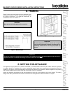
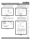
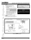
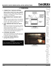
1. ATTACHING THE VENTING TO THE
APPLIANCE
To attach the first VP section to the appliance collars,
simply slide the flared end of the inner vent of the VP
section over the inner collar on the appliance. At the
same time, insert the outer vent into the outer collar
on the appliance. Push the vent section into the
appliance collar until all the lances have snapped in
place. Tug slightly on the vent to confirm it has
completely locked into place.
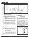
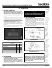
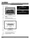
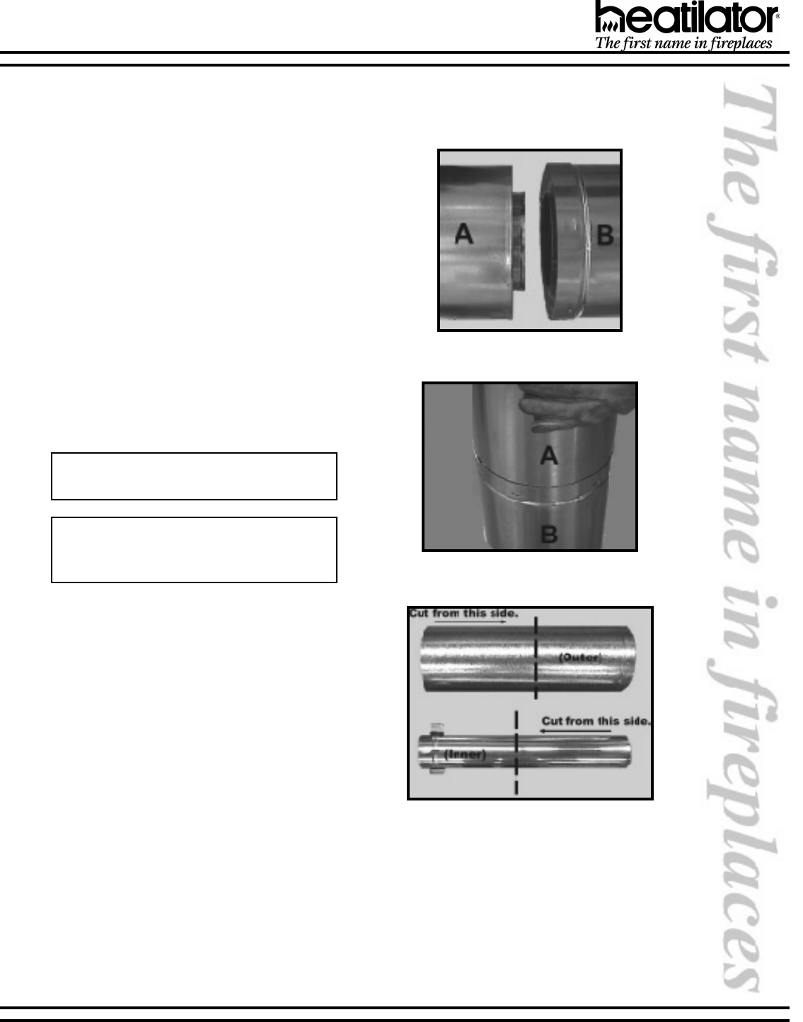
2. ASSEMBLING VENT SECTIONS
a. Start the flared inner flue of section A over the
inner flue of section B.
b. Insert the outer flue of section A into the outer
flue of section B. See Figure 19. Once both inner
and outer flues are started, press section A into
section B firmly until all lances have snapped
into place. Tug slightly on section A to confirm it
has completely locked into place. See Figure 20.
Note: Squeezing the pipe slightly to fit may be
necessary.
Note: Make sure that the seams are not per-
fectly aligned to prevent unintentional discon-
nection.
Figure 19
Figure 20
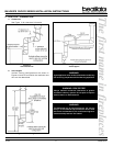
Figure 21
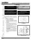
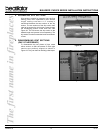
3. ASSEMBLING MINIMUM INSTALLATIONS
(MI) SECTIONS
MI sections are non-unitized so that they can be cut to
a certain length. To use these sections, they must be
cut to length from the non-expanded end. See Figure
21. They can then be attached by first connecting the
expanded end of the MI inner vent with the inner vent
from the adjacent vent section and securing with three
screws. The expanded portion of the MI inner vent must
overlap completely with the untreated end of the
adjacent vent section. The outer vent can then be
inserted into the adjacent outer vent expanded end
and attached to the next vent section with three screws.
The other end of the MI vent section can then be
attached by fitting a snap lock section to it and snapping
it together as normal.
G. ASSEMBLING VENT SECTIONS