


01-03 15 33606 Rev D
BUILDER'S CHOICE SERIES INSTALLATION INSTRUCTIONS
H. UTILITIES
1. GAS LINE CONNECTION
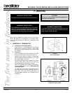
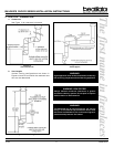
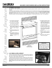
Open the control access panel as shown in Figure 24.
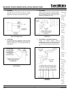
See Figure 25 to connect the gas line properly. All
connections must be checked for leaks with a soap
and water solution or a leak detector. Bleed the gas
line to extract any air that may have been trapped inside
the pipe.
This appliance is supplied with a 3/8 flare connection
to the gas valve. Installation of flexible connector and/
or manual gas valve must conform to local codes. In
the absence of local codes, with the National Flue Gas
Code ANSI Z223.1-latest edition in the U.S.A. and the
CAN/CGA B149 Installation Codes in Canada.
This appliance has been tested for installation of a
manual shutoff valve in the bottom compartment of the
appliance.
The Commonwealth of Massachusetts requires this
to be a T-handle type manual shutoff valve.
Note: This appliance and its manual shutoff valve must
be disconnected from the gas supply piping system dur-
ing any pressure testing of that system at test pressures
in excess of 1/2 psi (3.5 kPa). The appliance must be
isolated from the gas supply piping system by closing its
manual shutoff valve during any pressure testing of the
gas supply piping system at test pressures equal to or
less than 1/2 psi (3.5 kPa).
2. GAS PRESSURE
On the standing pilot gas control valve, a pressure tap
is included on the front face of the valve.
Table 2 shows the optimum gas pressure information.
Consult your local gas company for assistance in
determining the proper orifice for your altitude or refer
to ANSI Z223.1 - latest edition.
Table 2 - Gas Information for Standing Pilot Appliances
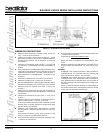
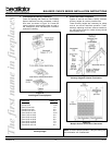
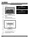
Figure 26 - Conversion Kit
63VDCB
.G.N.P.L
foesopruProferusserPtelnImuminiM
tnemtsujdAtupnI
*5.4*11
erusserPtelnImumixaM*5.01*41
erusserPdlofinaMlamitpO*5.3*01
erusserPdlofinaMmuminiM*7.1*4.5
H/UTBtupnImumixaM000,02005,81
sehcnI-eziSecifirO980.0250.0
nmuloCretaWfosehcnI*
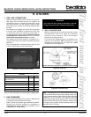
Figure 24 - Control Access Panel
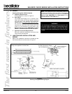
Figure 25 - Gas Line
Optional: Seal around the gas line to prevent cold air leakage.
(Right Side)
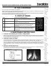
3. GAS CONVERSIONS
Natural or propane gas conversions necessary to meet
the application need to be made by a qualified
technician using Hearth & Home Technologies
specified and approved parts.
In the event your appliance must be converted to use
propane, you must use a CKP Conversion Kit. To be
converted to use natural gas, you must use a CKN
Conversion Kit. See Figure 26.
WARNING!
This valve has been preset at the factory. Altering
settings may result in fire hazard or bodily injury.