


Heat & Glo • Supreme-N-I30AU, Supreme-P-I30AU • 2222-900 Rev. P • 6/1238
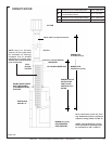
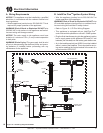
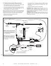
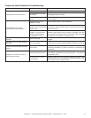
Figure10.2FanWiringDiagram
C. OptionalAccessoriesRequirements
• This appliance may be used with a wall switch, wall
mounted thermostat and/or a remote control.
• To connect optional accessories, the supplied cord as-
sembly should be used. See attached Figure 10.2 for
a wiring diagram for a blower or remote.
Wiring for optional Hearth & Home Technologies approved
accessories should be done now to avoid reconstruction.
Follow instructions that come with those accessories.
• Plug the cord into a convenient outlet.
• Must use cord supplied.
• An IntelliFire Plus™ Wireless Control or WSK-21 wired
wall switch may be used with the IntelliFire Plus™ Igni-
tion System.
• A standard ON/OFF switch is compatible.
WARNING! Risk of Shock! Label all wires prior to dis-
connection when servicing controls. Wiring errors can
cause improper and dangerous operation. Verify proper
operation after servicing.
WARNING! Risk of Shock! Replace damaged wire with
type 105 °C (221 °F) rated wire. Wire must have high
temperature insulation.
NOTE: USE ZIP TIES TO RESTRAIN
THE LOOSE WIRES UNDERNEATH
THE APPLIANCE AND KEEP THEM
AWAY FROM THE BLOWER WHEEL
(FAN BLADES).
NOTE: IF ANY OF THE ORIGINAL
WIRE AS SUPPLIED WITH THE
APPLIANCE MUST BE REPLACED,
IT MUST BE REPLACED WITH TYPE
105° C RATED WIRE.
PILOT OPTIONS
VALVE OPTIONS
FLAME
MODULATION
GROUND*
ORANGE
(PILOT)
GREEN
(MAIN)
MODULE (GRAY)
WIRE HARNESS
AUX300 MODULE
NG 2166-302
LP 2166-303
NG 2090-012
LP 2090-013
2166-304
2166-340
2166-306
BLACK
RED
JUMPER WIRE
2187-198
BATTERY PACK ASSEMBLY
4067-223
OPTIONAL
WALL SWITCH
OR
SURROUND
SWITCH
FAN ASSEMBLY
GFK210-240V
POWER CORD ASM
2222-374
SWITCHED DC
REGULATOR
2166-305
AUX1
AUX2
RED
* NOTE: GROUND FROM WIRE HARNESS
MUST BE ATTACHED TO UNPAINTED METAL
TO VALVE
GROUND
TERMINATION
WHITE
ORANGE
GAS TUBE
FLAME
SENSE
IGNITOR