


37Heat & Glo • Supreme-N-I30AU, Supreme-P-I30AU • 2222-900 Rev. P • 6/12
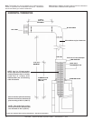
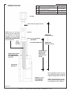
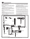
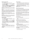
Figure10.1IPIWiringDiagramRC300AU
10
ElectricalInformation
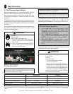
A. WiringRequirements
NOTICE: This appliance must be installed by a qualied
electrician in accordance with the relevant national and
local regulations.
• Wire the appliance junction box to 220-240 VAC. This is
required for proper operation of the appliance.
WARNING! Risk of Shock or Explosion! DO NOT wire
220/240 VAC to the valve or to the appliance wall switch.
Incorrect wiring will damage controls.
NOTICE: The main supply to the appliance must have
isolation of a minimum 1/8 in. (3 mm) contact separation
in both poles.
WARNING! Risk of Injury! The gas supply shall be shut
off prior to disconnecting the electrical power and remov-
ing batteries (if installed) before proceeding with any
maintenance to the appliance.
GREEN
(MAIN)
ORANGE
(PILOT)
8K1 WIRE
HARNESS
GROUND
CONTROL MODULE
DC REGULATOR
OPTIONAL ON/OFF
WALL SWITCH
RED
BLACK
CONNECTED
BATTERY PACK
6V DC (C X 4)
BROWN
TO OPTIONAL
COMPONENTS
TO JUNCTION
BOX 230 VAC
AUX300CE MODULE (OPTIONAL)
240V FAN (OPTIONAL)
FAN
AUX 1
AUX 2
S
I
GROUND
TO CHASSIS
TO AUX300CE
6V DC SUPPLY
RC100 6V DC
(CR2032 X 2)
(WALL SWITCH)
RC300 4.5V DC
(AAA X 3)
220/240 V
INCOMING POWER
GROUND
EMC FILTER UNIT
WHITE
ORANGE
GAS TUBE
FLAME
SENSE
IGNITOR
B. IntelliFirePlus
TM
IgnitionSystemWiring
• Wire the appliance junction box to 220-240 VAC for
proper operation of the appliance.
WARNING! Risk of Shock or Explosion! DO NOT wire
IPI controlled appliance junction box to a switched circuit.
Incorrect wiring will override IPI safety lockout.
• Refer to Figure 10.1, IPI Plus Wiring Diagram.
• This appliance is equipped with an IntelliFire Plus
TM
control valve which operates on a 6 volt/1.5 AMP system.
• Plug the 6 volt transformer plug into the appliance junction
box to supply power to the appliance OR install 4 C cell
batteries (not included) into the battery pack before use.
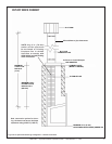
• An in-line isolation switch (per AS5601) must be installed
within 1 meter of the replace. This is required for servic-
ing and/or resetting the control module in the event of a
control module LOCK-OUT.