


29Heat & Glo • Supreme-N-I30AU, Supreme-P-I30AU • 2222-900 Rev. P • 6/12
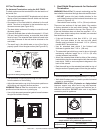
ImportantNotice: Heat shields may not be eld constructed.
120º
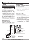
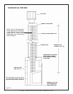
Figure8.12SecuringHorizontalPipeSections
• Horizontal sections must be supported every 5 ft. (1.52 m).
• Wall shield restops may be used to provide horizontal
support to vent sections.
WARNING! Risk of Fire, Explosion or Asphyxiation!
Improper support may allow vent to sag and separate.
Use vent run supports and connect vent sections per in-
stallation instructions. DO NOT allow vent to sag below
connection point to appliance.
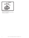
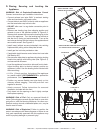
I. HeatShieldRequirementsforHorizontal
Termination
WARNING! Risk of Fire! To prevent overheating and re,
heat shields must extend through the entire wall thickness.
• DO NOT remove the heat shields attached to the
wall shield restop and the horizontal termination cap
(shown in Figure 8.10).
• Heat shields must overlap 1-1/2 in. (38 mm) minimum.
There are two sections of the heat shield. One section
is factory-attached to the wall shield restop. The other
section is factory-attached to the cap. See Figure 8.12.
If the wall thickness does not allow the required 1-1/2 in.
(38 mm) heat shield overlap when installed, an extended
heat shield must be used.
• If the wall thickness is less than 4-3/8 in. (111 mm)
(SLP), the heat shields on the cap and wall shield
restop must be trimmed. A minimum 1-1/2 in. (38 mm)
overlap MUST be maintained.
• Use an extended heat shield if the nished wall
thickness is greater than 7-1/4 in. (184 mm).
• The extended heat shield may need to be cut to length
maintaining sufcient length for a 1-1/2 in. (38 mm)
overlap between heat shields.
• Attach the extended heat shield to either of the existing
heat shields using the screws supplied with the extended
heat shield. Refer to vent components diagrams in the
back of this manual.
• Rest the small leg on the extended heat shield on top of
the pipe section to properly space it from the pipe section.
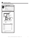
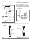
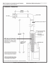
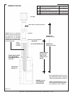
Figure8.10VentingthroughtheWall
• The termination kit should pass through the wall restops
from the exterior of the building.
• Adjust the termination cap to its nal exterior position on
the building and interlock the ue sections.
WARNING! Risk of Fire! the termination cap must be
positioned so that the arrow is pointing up.
• Use a high-temperature sealant gasket to seal between
the pipe and exterior restop.
EXTERIOR
INTERIOR
Interior
Wall Shield
Inner Flue
Rear Flue
Heat Shield
1-1/2 in.
(38 mm min)
overlap
Outer Flue
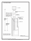
H.FlueTermination
For HorizontalTerminationsusingtheSLP-TRAP2
To attach and secure the termination to the last section of
horizontal ue:
• The rear ue heat shield MUST be placed one inch above
the top of the ue between the wall shield and the base
of the termination cap.
• One section of the heat shield is attached to the wall
shield. The other is attached to the termination cap in
the same manner (see Figure 8.10).
• The heat shield sections will overlap to match the wall
thickness (depth).
• If the wall thickness does not allow the required 1-1/2 inch
(38 mm) heat shield overlap, an extended heat shield
must be used. The extended heat shield will need to be
cut to the thickness of the wall and be attached to the
wall shield.
• The small leg in the shield rests on top of the ue to
properly space it from the pipe section (see Figure 8.10).
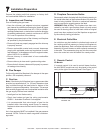
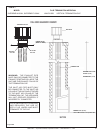
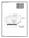
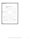
Figure8.11TerminationCap
1 in. (25 mm)
7-1/2 in.
(192 mm)
MINIMUM
CapSpecicationChart
(depthwithoutusingadditionalpipesections)
Supreme-N-AU
Supreme-P-AU
SLP-TRAP2
Rear Vent Depth
5-1/2in.(152mm)to9-1/2in.(241mm)