


Heat & Glo • Supreme-N-I30AU, Supreme-P-I30AU • 2222-900 Rev. P • 6/1236
9
GasInformation
A. GasPressureRequirements
Pressure requirements for Supreme-N-I30AU and Su-
preme-P-I30AU replaces are shown in table below.
Two taps are provided on the front of the gas control for
a test gauge connection to measure the inlet and outlet
pressures.
The replace and its individual shut-off valve must be dis-
connected from the gas supply piping system during any
pressure testing of the system at test pressures in excess
of 6 kPa.
If the replace must be isolated from the gas supply pip-
ing system by closing an individual shut-off valve, it must
be of the handle-less type.
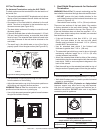
Incoming gas line should be piped into the valve compart-
ment and connected to the ISO 7-Rp 1/2 (BSP Rp 1/2)
threaded gas inlet connection on the manual shutoff valve.
B. GasConnection
Note: Have the gas supply line installed in accordance with
local building codes by a qualied installer approved and/or
licensed as required by the locality.
Note: Before the rst ring of the appliance, the gas supply
line should be purged of any trapped air.
Note: Consult local building regulations to properly size the
gas supply line leading to the (Rp 1/2 in.) hook-up at the unit.
WARNING
CHECK FOR GAS LEAKS
Explosion Risk
Fire Risk
Asphyxiation Risk
• Check all ttings and connections.
• Do not use open ame.
• After the gas line installation is complete, all
connections must be tightened and checked
for leaks with a commercially-available, non-
corrosive leak check solution. Be sure to rinse
off all leak check solution following testing.
Fittings and connections may have loosened
during shipping and handling.
WARNING
Fire Risk
Explosion Risk
High pressure will damage valve.
• Disconnect gas supply piping BEFORE
pressure testing gas line at test pressures
above 6 kPa.
• Close the manual shutoff valve BEFORE
pressure testing gas line at test pressures
equal to or less than 6 kPa.
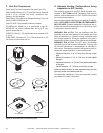
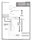
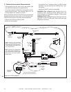
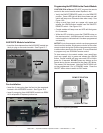
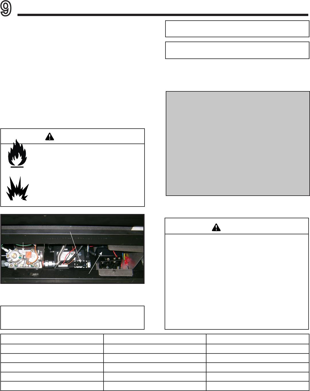
Figure11.1.ValveComponents
GAS VALVE
CONTROL
MODULE
ON/OFF/REMOTE
SWITCH
DC ADAPTER
Natural Gas Propane
Inlet Gas Pressure 1.13 - 3.40 kPa 2.75 - 3.40 kPa
Outlet (Manifold) Gas Pressure .80 - .95 kPa 2.36 - 2.61 kPa
Maximum Gas Consumption 31.9 MJ/h 30.9 MJ/h
Burner Injector DMS 36 (2.70 mm) DMS 52 (1.61 mm)
Pilot Injector .023 .014
An in-line regulator MUST be installed if the gas pressure exceeds 3.40kPa. Failure to install a regulator could damage
valve.
Leak test all gas line points and the gas control valve prior
to and after starting the gas appliance.
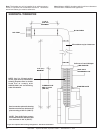
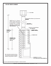
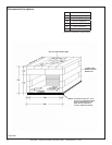
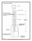
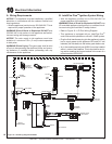
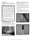
IMPORTANT NOTICE: (Items 1, 2 and 3 applies to
ALL Heat & Glo gas appliances)
1. 1/2 in. GAS LINE: Run through cavity 70 mm
above nished hearth level, NOT RIGID, NOT
CLIPPED, with minimum 500 mm into cavity and
120 mm back from plaster face.
2. PVC (COMPOSITE) GASLINE must terminate
minimum 500 mm short of gas heater. Copper pipe
MUST be the nal connection to the gas heater.
3. ISOLATING SWITCH: Location within 1 metre
of replace, subject to mantelpiece etc. Check to
ensure it remains clear of any mantelpiece instal-
lation.