


25Heat & Glo • Supreme-N-I30AU, Supreme-P-I30AU • 2222-900 Rev. P • 6/12
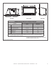
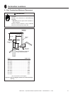
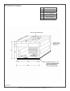
Figure8.4
REAR LEVELING LEGS
SHIPPED IN THIS POSITION
LOCATION A
REAR LEVELING LEGS MAY BE RELOCATED
TO LOCATION A OR LOCATION B
LOCATION B
WARNING! Risk of Fire! Only an approved Hearth &
Home Technologies surround may be used to cover inte-
gral grills on solid fuel burning replaces. No other com-
ponents such as shrouds, sheetmetal plates, etc., may be
used to seal off vents.
WARNING! Risk of Explosion! Failure to position the
parts in accordance with these diagrams or failure to use
only parts specically approved with this appliance may
result in property damage or personal injury.
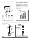
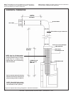
WARNING! Risk of Explosion/Combustion Fumes!
Connect vent sections per installation instructions.
• Connect exhaust vent pipe ONLY to exhaust starting
collar and termination cap center collar.
• Connect inlet air vent ONLY to inlet air collar on appliance
and the termination cap inlet air collar.
• DO NOT allow vent to sag below connection point to
appliance.
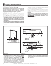
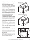
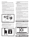
• Remove rear leveling legs from shipping position and
relocate to one of the positions shown in Figure 8.3.
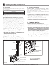
Remove both screws that secure the leveling leg to the
side of the appliance. Turn the leveling leg around so
that the foot is facing out and downward. Line up the
two holes on the leg with the holes on the appliance and
secure with screws. See Figure 8.3.
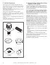
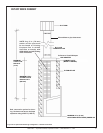
• Install insert (without surround attached) into existing
replace while pulling collar slide plate forward.
• Install gas line into hole provided on side.
• If applicable install remote control wires into insert side
See Section 8.E.
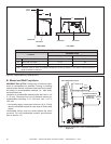
• Secure collar slide plate to appliance by placing locking
handle into position with locking tabs (see Figure 8.1)
and secure with #8 screw.
• Level the appliance from side to side and front to back.
Adjust leveling bolts to desired vertical position so
appliance is level. Use the leveling bolts included with
the manual bag.
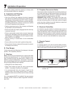
• A 1/2 in. (13 mm) gap from the bottom of the appliance
to a metal surface is RECOMMENDED for optimal fan
performance. See Figure 5.1.
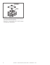
• Position any excess exible vent pipe back up into
chimney without sagging. Twist and push flex vent
together to shorten.
• Attach surround. Follow instructions for surround
installation included with the front.
• Push insert into the opening so that it tightly overlaps
the replace opening.
D. Placing, Securing and Leveling the
Appliance