


Heat & Glo • LUX60 • 4062-116 • Rev. G • 4/1122
5
5
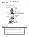
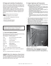
Framing and Clearances
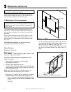
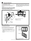
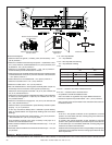
A. Select Appliance Location
When selecting a location for the appliance it is important
to consider the required clearances to walls (see
Figure 5.1).
WARNING! Risk of Fire or Burns! Provide adequate
clearance around air openings and for service access. Due
to high temperatures, the appliance should be located out
of traffi c and away from furniture and draperies.
NOTICE: Illustrations refl ect typical installations and are
FOR DESIGN PURPOSES ONLY. Illustrations/diagrams
are not drawn to scale. Actual installation may vary due to
individual design preference.
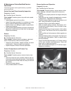
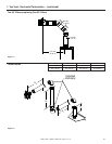
52 in.
(1321 mm)
1.5 in. (114 mm)
1.5 in.
(114 mm)
31 in.
(787 mm)
69-3/4 in.
(1772 mm)
69-3/4 in.
(1772 mm)
1.5 in.
(114 mm)
1.5 in.
(114 mm)
1.5 in.
(114 mm)
Top Vent
One 90° elbow
Horiz Term
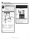
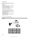
In addition to these framing dimensions, also
reference the following sections:
• Clearances
• Vent Clearances and Framing
52 in.
(1321 mm)
98-5/8 in.
(2505 mm)
12 in.
(305 mm)
Figure 5.1 Appliance Locations
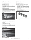
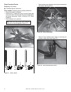
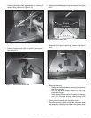
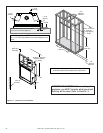
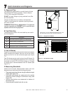
B. Assemble Steel Stud Kit
You must assemble and install the steel stud kit and at-
tach the noncombustible cement board (provided), The
steel track and studs are precut to the correct lengths.
• Lay out steel track and studs per Figure 5.2.
• Fasten track and studs together with the pierce-point
screws to construct a 52 x 36 in. (1321 x 914 mm)
assembly.
• Attach steel stud assembly to framing as shown in
Figure 9.1.
4 Studs
16 Screws
(8 each side)
2 tracks
Assembled
Figure 5.2 Steel Track and Studs