


Heat & Glo • LUX60 • 4062-116 • Rev. G • 4/11 21
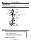
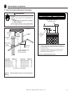
B. Design and Installation Considerations
Heat & Glo direct vent gas appliances are designed to op-
erate with all combustion air siphoned from outside of the
building and all exhaust gases expelled to the outside. No
additional outside air source is required.
Installation MUST comply with local, regional, state and
national codes and regulations. Consult insurance carrier,
local building inspector, fi re offi cials or authorities having
jurisdiction over restrictions, installation inspection and
permits.
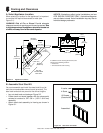
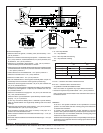
Before installing, determine the following:
• Where the appliance is to be installed.
• The vent system confi guration to be used.
• Gas supply piping.
• Electrical wiring requirements.
• Framing and fi nishing details.
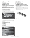
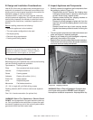
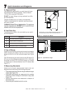
D. Inspect Appliance and Components
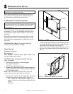
• Carefully remove the appliance and components from
the packaging (refer to Figure 4.2).
- Remove steel stud kit. Remove the shipping strap
holding the cement board in place by removing the
screws. Discard strap, replace screws.
- Remove screws holding four shipping brackets to
pallet before trying to move unit.
- Remove the three packages of glass rock from the
top of the unit and the shipping spacer from the top
of the fl ue.
- Remove screw from top of each carrying handle.
Handles have been provided to assist in moving the
unit.
• The vent system components and decorative doors and
fronts are shipped in separate packages.
• Report to your dealer any parts damaged in shipment,
particularly the condition of the glass.
• Read all of the instructions before starting the installation.
Follow these instructions carefully during the installation
to ensure maximum safety and benefi t.
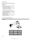
C. Tools and Supplies Needed
Before beginning the installation be sure that the following
tools and building supplies are available.
Tape measure Framing material
Pliers Non-corrosive leak check solution
Hammer Phillips screwdriver
Gloves Framing square
Voltmeter Electric drill and bits (1/4 in.)
Plumb line Safety glasses
Level Reciprocating saw
Manometer Flat blade screwdriver
1/2 - 3/4 in. length, #6 or #8 Self-drilling screws
Caulking material (300ºF minimum continuous exposure
rating)
One 1/4 in. female connection (for optional fan).
WARNING! Risk of Fire, Explosion or Electric Shock!
DO NOT use this appliance if any part has been under wa-
ter. Call a qualifi ed service technician to inspect the appli-
ance and to replace any part of the control system and/or
gas control which has been under water.
Improper installation, adjustment, alteration, service or
maintenance can cause injury or property damage. For
assistance or additional information, consult a qualifi ed
service technician, service agency or your dealer.
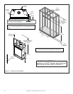
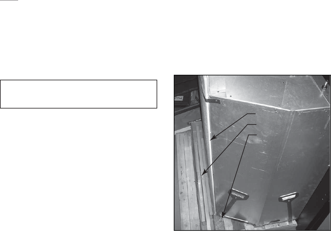
Steel Stud Kit
1/2 in. Cement Board
Shipping Bracket
Figure 4.2 Shipping Locations
WARNING! Risk of Fire or Explosion! Damaged parts
could impair safe operation. DO NOT install damaged,
incomplete or substitute components. Keep appliance dry.