


9
Installation, Operation & Maintenance HTV/HTD/HTH SERIES Heat Controller, Inc.
Vertical Installation
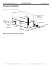
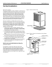
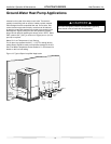
Figure 7: Vertical Unit Mounting
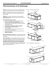
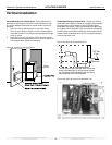
Figure 8: Typical Vertical Unit Installation Using Ducted
Return Air
$LU3DGRUH[WUXGHG
SRO\VW\UHQHLQVXODWLRQERDUG
Flexible canvas duct
connector to reduce
noise and vibration
Use turning vanes in
supply transition
Internally insulate supply
duct for first 1.2 m each way
to reduce noise
Internally insulate return
transition duct to reduce
noise
Rounded return
transition
Rev.: 6/2/09S
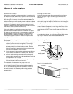
Vertical Unit Location
Units are not designed for outdoor installation. Locate the unit in
an INDOOR area that allows enough space for service personnel
to perform typical maintenance or repairs without removing unit
from the mechanical room/closet. Vertical units are typically
installed in a mechanical room or closet. Never install units in
areas subject to freezing or where humidity levels could cause
cabinet condensation (such as unconditioned spaces subject to
100% outside air). Consideration should be given to access for
easy removal of the fi lter and access panels. Provide suffi cient
room to make water, electrical, and duct connection(s).
If the unit is located in a confi ned space, such as a closet,
provisions must be made for return air to freely enter the space
by means of a louvered door, etc. Any access panel screws that
would be diffi cult to remove after the unit is installed should
be removed prior to setting the unit. Refer to Figures 7 and 8
for typical installation illustrations. Refer to unit specifi cations
catalog for dimensional data.
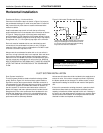
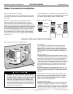
1.
Install the unit on a piece of rubber, neoprene or other
mounting pad material for sound isolation. The pad should
be at least 3/8” [10mm] to 1/2” [13mm] in thickness. Extend
the pad beyond all four edges of the unit.
2. Provide adequate clearance for fi lter replacement and drain
pan cleaning. Do not block fi lter access with piping, conduit
or other materials. Refer to unit specifi cations for dimensional
data.
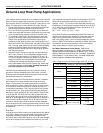
3. Provide access for fan and fan motor maintenance and for
servicing the compressor and coils without removing the unit.
4. Provide an unobstructed path to the unit within the closet
or mechanical room. Space should be suffi cient to allow
removal of the unit, if necessary.
5. Provide access to water valves and fi ttings and screwdriver
access to the unit side panels, discharge collar and all
electrical connections.
Downfl ow units may be installed directly on the fl oor. The
optional internal electric heat is rated for zero clearance to
combustible materials.
The installation of water source heat pump units and all
associated components, parts and accessories which make
up the installation shall be in accordance with the regulations
of ALL authorities having jurisdiction and MUST conform to
all applicable codes. It is the responsibility of the installing
contractor to determine and comply with ALL applicable codes
and regulations.