


18
Installation, Operation & Maintenance HTV/HTD/HTH SERIES Heat Controller, Inc.
Warning! The HWG pump Is fully wired from the factory. Use
extreme caution when working around the microprocessor
control as it contains line voltage connections that presents
a shock hazard that can cause severe injury or death!
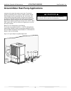
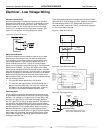
The heat pump, water piping, pump, and hot water tank should
be located where the ambient temperature does not fall below
50°F [10°C]. Keep water piping lengths at a minimum. DO NOT
use a one way length greater than 50 ft. (one way) [15 m]. See
Table 7 for recommended piping sizes and maximum lengths.
All installations must be in accordance with local codes. The
installer is responsible for knowing the local requirements, and
for performing the installation accordingly. DO NOT connect the
pump wiring until “Initial Start-Up” section, below. Powering the
pump before all installation steps are completed may damage the
pump.
Water Tank Preparation
1. Turn off power or fuel supply to the hot water tank.
2. Connect a hose to the drain valve on the water tank.
3. Shut off the cold water supply to the water tank.
4. Open the drain valve and open the pressure relief valve or a
hot water faucet to drain tank.
5. When using an existing tank, it should be fl ushed with cold
water after it is drained until the water leaving the drain hose
is clear and free of sediment.
6. Close all valves and remove the drain hose.
7. Install HWG water piping.
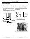
HWG Water Piping
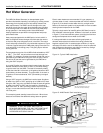
1. Using at least 5/8” [16mm] O.D. copper, route and install the
water piping and valves as shown in Figures 14 or 15. Install
an approved anti-scald valve if the 150°F HWG setpoint is or
will be selected. An appropriate method must be employed
to purge air from the HWG piping. This may be accomplished
by fl ushing water through the HWG (as In Figures 14 and
15) or by Installing an air vent at the high point of the HWG
piping system.
2. Insulate all HWG water piping with no less than 3/8” [10mm]
wall closed cell insulation.
3. Open both shut off valves and make sure the tank drain valve
is closed.
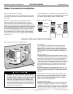
Water Tank Refi ll
1. Close valve #4. Ensure that the HWG valves (valves #2 and
#3) are open. Open the cold water supply (valve #1) to fi ll the
tank through the HWG piping. This will purge air from the
HWG piping.
2. Open a hot water faucet to vent air from the system until
water fl ows from faucet; turn off faucet. Open valve #4.
3.
Depress the hot water tank pressure relief valve handle to
ensure that there is no air remaining in the tank.
4. Inspect all work for leaks.
5.
Before restoring power or fuel supply to the water heater,
adjust the temperature setting on the tank thermostat(s) to
insure maximum utilization of the heat available from the
refrigeration system and conserve the most energy. On tanks
with both upper and lower elements and thermostats, the
lower element should be turned down to 100°F [38°C] or
the lowest setting; the upper element should be adjusted to
120-130°F [49-54°C]. Depending upon the specifi c needs
of the customer, you may want to adjust the upper element
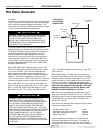
differently. On tanks with a single thermostat, a preheat tank
should be used (Fig 15).
6. Replace access cover(s) and restore power or
fuel supply.
Initial Start-Up
1. Make sure all valves in the HWG water circuit are
fully open.
2. Turn on the heat pump and allow it to run for
10-15 minutes.
3. Set SW12 to the “OFF” position (enabled) to engage the
HWG.
4. The HWG pump should not run if the compressor is not
running.
5. The temperature difference between the water entering and
leaving the HWG coil should be approximately 5-10°F [3-
6°C].
6. Allow the unit to operate for 20 to 30 minutes to insure that it
is functioning properly.
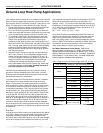
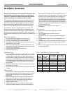
Hot Water Generator
Table 7: HWG Water Piping Sizes and Length
Unit
Nominal
Tonnage
Nominal
HWG Flow
(gpm)
1/2" Copper
(max length*)
3/4" Copper
(max length*)
1.5 0.6 50 -
2.0 0.8 50 -
2.5 1.0 50 -
3.0 1.2 50 -
3.5 1.4 50 -
4.0 1.6 45 50
5.0 2.0 25 50
6.0 2.4 10 50
*Maximum length is equivalent length (in feet) one way of type L copper.