


14
Installation, Operation & Maintenance HTV/HTD/HTH SERIES Heat Controller, Inc.
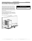
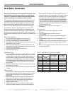
$LU3DGRU
([WUXGHG
SRO\VW\UHQH
LQVXODWLRQERDUG
8QLW3RZHU
'LVFRQQHFW
7KHUPRVWDW
:LULQJ
3UHVVXUH
7DQ N
6KXW2II
9DOYH
%RLOHU
'UDLQV
)ORZ
5HJXODWRU
:DWHU,Q
:DWHU2XW
:DWHU
&RQWURO
9DOYH
2SWLRQDO
)LOWHU
373OXJV
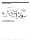
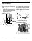
Figure 13: Typical Open Loop/Well Application
Ground-Water Heat Pump Applications
mounted on the outlet of the water control valve. The device is
typically a brass fi tting with an orifi ce of rubber or plastic material
that is designed to allow a specifi ed fl ow rate. On occasion, fl ow
control devices may produce velocity noise that can be reduced
by applying some back pressure from the ball valve located on the
discharge line. Slightly closing the valve will spread the pressure
drop over both devices, lessening the velocity noise. NOTE: When
EWT is below 50°F [10°C], a minimum of 2 gpm per ton (2.6 l/m
per kW) is required.
Water Coil Low Temperature Limit Setting
For all open loop systems the 30°F [-1.1°C] FP1 setting (factory
setting-water) should be used to avoid freeze damage to the unit.
See “Low Water Temperature Cutout Selection” in this manual for
details on the low limit setting.
CAUTION!
CAUTION! Refrigerant pressure activated water regulating
valves should never be used with this equipment.