


23
Installation, Operation & Maintenance HTV/HTD/HTH SERIES Heat Controller, Inc.
Electrical - Thermostat Wiring
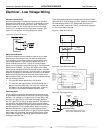
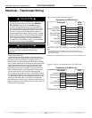
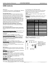
Figure 24: Units With Optional ECM Fan.
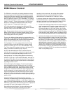
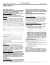
Figure 25: Typical Thermostat 2 Heat/1 Cool (PSC Fan)
Thermostat Installation
The thermostat should be located on an interior wall in a
larger room, away from supply duct drafts. DO NOT locate
the thermostat in areas subject to sunlight, drafts or on
external walls. The wire access hole behind the thermostat
may in certain cases need to be sealed to prevent erroneous
temperature measurement. Position the thermostat back
plate against the wall so that it appears level and so the
thermostat wires protrude through the middle of the back
plate. Mark the position of the back plate mounting holes
and drill holes with a 3/16” (5mm) bit. Install supplied
anchors and secure plate to the wall. Thermostat wire must
be 18 AWG wire. Wire the appropriate thermostat as shown
in Figures 24 and 25 to the low voltage terminal strip on the
CXM (units with PSC motor) or ECM control board (units
with ECM motor). Practically any heat pump thermostat will
work with these units, provided it has the correct number of
heating and cooling stages.
ATP32U04 Thermostat
Connection to ECM Control
Compressor
Compressor Stage 2
Reversing Valve
Fan
24Vac Hot
24Vac Common
Fault LED
ECM
Board
Y1
Y2
W
DH
O
G
R
C
AL1
Y1
Y2
W
DH
O
G
R
C
L
Dehumidification
Units with CXM or DXM board and ECM fan motor, utilizing ECM dehumidification
mode (without ClimaDry option)
Notes:
1) Units with whole house dehumidification option have slightly different
thermostat wiring.Terminal DH at the thermostat is connected to terminal H at
the DXM board
2) ECM dehumidification mode slows down fan speed in the cooling mode when
dehumidification output from thermostat is active. Normal heating and cooling fan
speeds are not affected.
3) ECM board DIP switch SW9 must be in dehumid. mode for
ECM dehumidification mode.
Auxiliary Heat
ATM21U01 Thermostat
Connection to CXM Control
Compressor
Heating Stage 2
Reversing Valve
Fan
24Vac Hot
24Vac Common
Fault LED
Y
Y2/W
O
G
R
C
L
Y
W
O
G
R
C
AL1
CXM
NOTICE: Units with ClimaDry whole house dehumidiÄ cation
option require a separate humidistat or thermostat part
number ATP32U04 (See ClimaDry AOM for more details).
ѥCAUTION! ѥ
ѥCAUTION! ѥ
CAUTION! Refrigerant pressure activated water regulating
valves should never be used with ClimateMaster
equipment.
CAUTION! Many units are installed with a factory or ¿ eld
supplied manual or electric shut-off valve. DAMAGE
WILL OCCUR if shut-off valve is closed during unit
operation. A high pressure switch must be installed on
the heat pump side of any ¿ eld provided shut-off valves
and connected to the heat pump controls in series with
the built-in refrigerant circuit high pressure switch to
disable compressor operation if water pressure exceeds
pressure switch setting. The ¿ eld installed high pressure
switch shall have a cut-out pressure of 300 psig and a
cut-in pressure of 250 psig. This pressure switch can
be ordered from ClimateMaster with a 1/4” internal À are
connection as part number 39B0005N02.
Manufacturer
Manufacturer
Units with CXM or DXM board and ECM fan motor, utilizing ECM dehumidifi cation mode
Notes:
1) ECM dehumidifi cation mode slows down fan speed in the cooling mode when
dehumidifi cation output from thermostat is active. Normal heating and cooling fan
speeds are not affected.
2) ECM board DIP switch SW9 must be in dehumid. mode for ECM dehumidifi cation mode.