


10
Installation, Operation & Maintenance HTV/HTD/HTH SERIES Heat Controller, Inc.
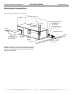
Vertical Installation
Return
Air Inlet
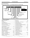
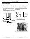
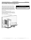
Figure 9: Vertical Sound Attenuation
ರ
ರ
ರ
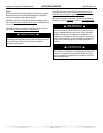
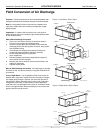
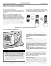
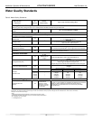
* Some units include a painted drain connection.
Using a threaded pipe or similar device to clear
any excess paint accumulated inside this fitting
may ease final drain line installation.
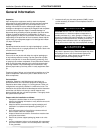
ರ3HU
)RRW
Figure 10a: Vertical Condensate Drain
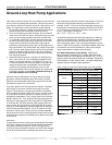
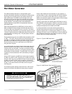
Figure 10b: Vertical Internal Condensate Trap
Condensate Piping for Vertical Units - Vertical units utilize a
condensate hose inside the cabinet as a trapping loop; therefore
an external trap is not necessary. Figure 10a shows typical
condensate connections. Figure 10b illustrates the internal trap
for a typical vertical heat pump. Each unit must be installed with
its own individual vent (where necessary) and a means to fl ush
or blow out the condensate drain line. Do not install units with a
common trap and/or vent.
Sound Attenuation for Vertical Units - Sound attenuation is
achieved by enclosing the unit within a small mechanical room
or a closet. Additional measures for sound control include the
following:
1. Mount the unit so that the return air inlet is 90° to the
return air grille. Refer to Figure 9. Install a sound baffl e as
illustrated to reduce line-of sight sound transmitted through
return air grilles.
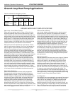
2.
Mount the unit on an Unit Isolation Pad to minimize vibration
transmission to the building structure. For more information on
Unit Isolation Pads, contact your distributor.