


8
Installation, Operation & Maintenance HTV/HTD/HTH SERIES Heat Controller, Inc.
ರ
ರ
ರ
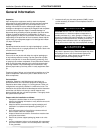
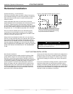
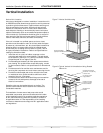
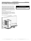
* Some units include a painted drain connection.
Using a threaded pipe or similar device to clear
any excess paint accumulated inside this fitting
may ease final drain line installation.
ರ3HU
)RRW
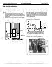
Figure 6: Horizontal Condensate Connection
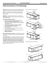
Horizontal Installation
Condensate Piping – Horizontal Units
Pitch the unit toward the drain as shown in Figure 2 to improve
the condensate drainage. On small units (less than 2.5 tons/8.8
kW), insure that unit pitch does not cause condensate leaks
inside the cabinet.
Install condensate trap at each unit with the top of the trap
positioned below the unit condensate drain connection as shown
in Figure 6. Design the depth of the trap (water-seal) based
upon the amount of ESP capability of the blower (where 2 inches
[51mm] of ESP capability requires 2 inches [51mm] of trap depth).
As a general rule, 1-1/2 inch [38mm] trap depth is the minimum.
Each unit must be installed with its own individual trap and
connection to the condensate line (main) or riser. Provide a
means to fl ush or blow out the condensate line. DO NOT install
units with a common trap and/or vent.
Always vent the condensate line when dirt or air can collect in
the line or a long horizontal drain line is required. Also vent when
large units are working against higher external static pressure
than other units connected to the same condensate main since
this may cause poor drainage for all units on the line. WHEN A
VENT IS INSTALLED IN THE DRAIN LINE, IT MUST BE LOCATED
AFTER THE TRAP IN THE DIRECTION OF THE CONDENSATE
FLOW.
CAUTION!
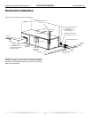
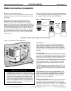
Duct System Installation
The duct system should be sized to handle the design airfl ow
quietly. Refer to Figure 3 for horizontal duct system details or
fi gure 8 for vertical duct system details. A fl exible connector is
recommended for both discharge and return air duct connections
on metal duct systems to eliminate the transfer of vibration to
the duct system. To maximize sound attenuation of the unit
blower, the supply and return plenums should include internal
fi berglass duct liner or be constructed from ductboard for the
fi rst few feet. Application of the unit to uninsulated ductwork
in an unconditioned space is not recommended, as the unit’s
performance will be adversely affected.
At least one 90° elbow should be included in the supply duct to
reduce air noise. If air noise or excessive air fl ow is a problem,
the blower speed can be changed. For airfl ow charts, consult
specifi cations catalog for the series and model of the specifi c
unit.
If the unit is connected to existing ductwork, a previous check
should have been made to insure that the ductwork has the
capacity to handle the airfl ow required for the unit. If ducting is
too small, as in the replacement of a heating only system, larger
ductwork should be installed. All existing ductwork should be
checked for leaks and repaired as necessary.
DUCT SYSTEM INSTALLATION
C
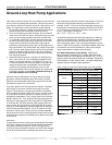
ondensate Pipin
g
CAUTION! Ensure condensate line is pitched toward drain
1/8 inch per ft [11mm per m] of run.