


17
Installation, Operation & Maintenance HTV/HTD/HTH SERIES Heat Controller, Inc.
Hot Water Generator
The microprocessor control monitors the refrigerant and
water temperatures to determine when to operate the HWG.
The HWG will operate any time the refrigerant temperature
is sufÄ ciently above the water temperature. Once the
HWG has satisÄ ed the water heating demand during a
heat pump run cycle, the controller will cycle the pump at
regular Intervals to determine if an additional HWG cycle
can be utilized. The microprocessor control Includes 3 DIP
switches, SW10 (HWG PUMP TEST), SW11 (HWG TEMP),
and SW12 (HWG STATUS).
SW10 HWG PUMP TEST. When this switch is in the “ON”
position, the HWG pump is forced to operate even if there
is no call for the HWG. This mode may be beneÄ cial to
assist in purging the system of air during Initial start up.
When SW10 is in the “OFF” position, the HWG will operate
normally. This switch is shipped from the factory in the
“OFF” (normal) position. NOTE; If left in the “On” position for
5 minutes, the pump control will revert to normal operation.
SW11 HWG TEMP. The control setpoint of the HWG can
be set to either of two temperatures, 125°F or 150°F. When
SW11 is in the “ON” position the HWG setpoint is 150°F.
When SW11 is in the “OFF” position the HWG setpoint is
ѥWARNING! ѥ
ѥWARNING! ѥ
WARNING!
UNDER NO CIRCUMSTANCES SHOULD
THE SENSORS BE DISCONNECTED OR REMOVED
AS FULL LOAD CONDITIONS CAN DRIVE HOT
WATER TANK TEMPERATURES FAR ABOVE SAFE
TEMPERATURE LEVELS IF SENSORS HAVE BEEN
DISCONNECTED OR REMOVED.
WARNING!
USING A 150°F SETPOINT ON THE
HWG WILL RESULT IN WATER TEMPERATURES
SUFFICIENT TO CAUSE SEVERE PHYSICAL INJURY
IN THE FORM OF SCALDING OR BURNS, EVEN
WHEN THE HOT WATER TANK TEMPERATURE
SETTING IS VISIBLY SET BELOW 150°F. THE 150°F
HWG SETPOINT MUST ONLY BE USED ON SYSTEMS
THAT EMPLOY AN APPROVED ANTI-SCALD VALVE
(PART NUMBER AVAS4) AT THE HOT WATER
STORAGE TANK WITH SUCH VALVE PROPERLY
SET TO CONTROL WATER TEMPERATURES
DISTRIBUTED TO ALL HOT WATER OUTLETS AT A
TEMPERATURE LEVEL THAT PREVENTS SCALDING
OR BURNS!
125°F. This switch Is shipped from the factory in the “OFF”
(125°F) position.
SW12 HWG STATUS. This switch controls operation of
the HWG. When SW12 is in the “ON” position the HWG is
disabled and will not operate. When SW12 is in the “OFF”
position the HWG is in the enabled mode and will operate
normally. This switch is shipped from the factory in the
“ON” (disabled) position. CAUTION: DO NOT PLACE THIS
SWITCH IN THE ENABLED POSITION UNITL THE HWG
PIPING IS CONNECTED, FILLED WITH WATER, AND
PURGED OR PUMP DAMAGE WILL OCCUR.
When the control is powered and the HWG pump output
is not active, the status LED (AN1) will be “On”. When the
HWG pump output is active for water temperature sampling
or HWG operation, the status LED will slowly Å ash (On 1
second, Off 1 second).
If the control has detected a fault, the status LED will Å ash a
numeric fault code as follows:
Hot Water Sensor Fault 1 Å ash
Compressor Discharge sensor fault 2 Å ashes
High Water Temperature (>160ºF) 3 Å ashes
Control Logic Error 4 Å ashes
Fault code Å ashes have a duration of 0.4 seconds with
a 3 second pause between fault codes. For example, a
“Compressor Discharge sensor fault” will be four Å ashes
0.4 seconds long, then a 3 second pause, then four Å ashes
again, etc.
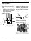
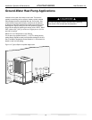
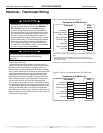
C
H
M
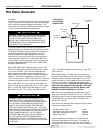
WATER HEATER
CHECK VALVE
8” MAX
HOT WATER
TO HOUSE
ANTI-SCALD
VALVE
ANTI-SCALD
VALVE PIPING
CONNECTIONS
COLD WATER
SUPPLY
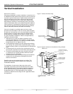
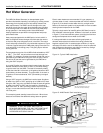
Installation
The HWG is controlled by two sensors and a microprocessor
control. One sensor is located on the compressor discharge
line to sense the discharge refrigerant temperature. The
other sensor is located on the HWG heat exchanger’s “Water
In” line to sense the potable water temperature.