


20
Installation, Operation & Maintenance HTV/HTD/HTH SERIES Heat Controller, Inc.
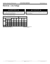
Electrical - Line Voltage
Electrical - Line Voltage
All fi eld installed wiring, including electrical ground, must comply
with the National Electrical Code as well as all applicable local
codes. Refer to the unit electrical data for fuse sizes. Consult
wiring diagram for fi eld connections that must be made by the
installing (or electrical) contractor.
All fi nal electrical connections must be made with a length of
fl exible conduit to minimize vibration and sound transmission to
the building.
General Line Voltage Wiring
Be sure the available power is the same voltage and phase shown
on the unit serial plate. Line and low voltage wiring must be done
in accordance with local codes or the National Electric Code,
whichever is applicable.
WARNING!
CAUTION!
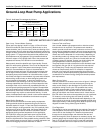
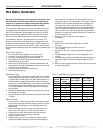
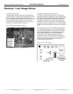
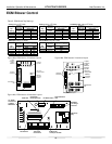
Unit Power Supply
(see electrical table for wire
and breaker size)
Connect the blue wire to:
H for High speed fan
M for Medium speed fan
L for Low speed fan
Medium is factory setting
Fan Motor
Figure 17: PSC Motor Speed Selection
WARNING! Disconnect electrical power source to prevent
injury or death from electrical shock.
CAUTION! Use only copper conductors for fi eld installed
electrical wiring. Unit terminals are not designed to accept
other types of conductors.
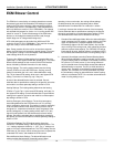
Blower Speed Selection – Units with PSC Motor
PSC (Permanent Split Capacitor) blower fan speed can be
changed by moving the blue wire on the fan motor terminal
block to the desired speed as shown in Figure 17. Optional ECM
motor speeds are set via low voltage controls (see “ECM Blower
Control”). Most units are shipped on the medium speed tap.
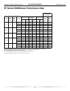
Consult specifi cations catalog for specifi c unit airfl ow tables.
Typical unit design delivers rated airfl ow at nominal static (0.15 in.
w.g. [37Pa]) on medium speed and rated airfl ow at a higher static
(0.4 to 0.5 in. w.g. [100 to 125 Pa]) on high speed for applications
where higher static is required. Low speed will deliver
approximately 85% of rated airfl ow at 0.10 in. w.g. [25 Pa].
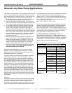
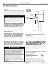
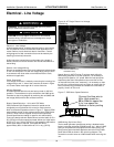
Power Connection
Line voltage connection is made by connecting the incoming line
voltage wires to the “L” side of the contactor as shown in Figure
16. Consult Tables 4a through 4b for correct fuse size.
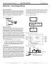
208 Volt Operation
All residential 208-230 Volt units are factory wired for 230 Volt
operation. The transformer may be switched to the 208V tap as
illustrated on the wiring diagram by switching the red (208V) and
the orange (230V) wires at the contactor terminal.
Special Note for AHRI Testing: To achieve rated airfl ow for
AHRI testing purposes on all PSC products, it is necessary to
change the fan speed to “HI” speed. When the heat pump has
experienced less than 100 operational hours and the coil has
not had suffi cient time to be “seasoned”, it is necessary to clean
the coil with a mild surfactant such as Calgon to remove the oils
left by manufacturing processes and enable the condensate to
properly “sheet” off of the coil.
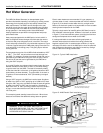
HWG Wiring (Split Units Only)
The hot water generator pump power wiring is disabled at the
factory to prevent operating the HWG pump “dry.” After all HWG
piping is completed and air purged from the water piping, the
pump power wires should be applied to terminals on the HWG
power block PB2 as shown in the unit wiring diagram. This
connection can also serve as a HWG disable when servicing the
unit.
Figure 16: HT Single Phase Line Voltage
Field Wiring