


21
Installation, Operation & Maintenance HTV/HTD/HTH SERIES Heat Controller, Inc.
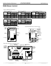
Electrical - Low Voltage Wiring
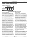
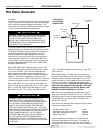
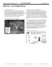
Low voltage Ä eld wiring for units with ECM fan
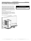
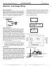
Low voltage
Ä eld wiring
for units with
PSC FAN
(ECM board
will not be
present)
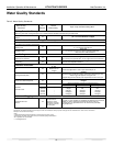
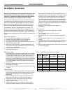
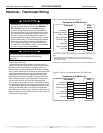
Figure 19: FP1 Limit Setting
CXM PCB
JW3-FP1
jumper should
be clipped for
low temperature
operation
Figure 18: TT/TS Low Voltage Field Wiring
Low Water Temperature Cutout Selection
The CXM control allows the Ä eld selection of low water (or
water-antifreeze solution) temperature limit by clipping jumper
JW3, which changes the sensing temperature associated with
thermistor FP1. Note that the FP1 thermistor is located on
the refrigerant line between the coaxial heat exchanger and
expansion device (TXV). Therefore, FP1 is sensing refrigerant
temperature, not water temperature, which is a better indicatio
n
of how water Å ow rate/temperature is affecting the refrigeration
circuit.
The factory setting for FP1 is for systems using water (30°F
[-1.1°C] refrigerant temperature). In low water temperature
(extended range) applications with antifreeze (most ground
loops), jumper JW3 should be clipped as shown in Figure
19 to change the setting to 10°F [-12.2°C] refrigerant
temperature, a more suitable temperature when using
an antifreeze solution. All residential units include water/
refrigerant circuit insulation to prevent internal condensation,
which is required when operating with entering water
temperatures below 59°F [15°C].
Thermostat Connections
The thermostat should be wired directly to the CXM board
(units with PSC fan). Units with optional ECM motor include
factory wiring from the CXM board to the ECM interface
board. Thermostat wiring for these units should be connected
to the ECM interface board. Figure 18 shows wiring for TT/
TS units with PSC or optional ECM motor. See “Electrical –
Thermostat” for speciÄ c terminal connections.
HT Low Voltage Field Wiring
HT